Vortech 1994-1995 Ford 5.0 Mustang User Manual
Page 17
P/N: 4FG020-010
© 2008 Vortech Engineering, Inc.
All Rights Reserved. Intl. Copr. Secured
04NOV08 V2.0(94-95 5.0 Mus.(4FG V2.0))
9
A. Attach the supplied 5/8" coolant hose with the
molded elbow end to the heater fitting on the
firewall. Secure with a hose clamp.
B. Carefully route the coolant hose along the shock
tower and fuel lines next to the oil fill pipe and
secure with cable ties.
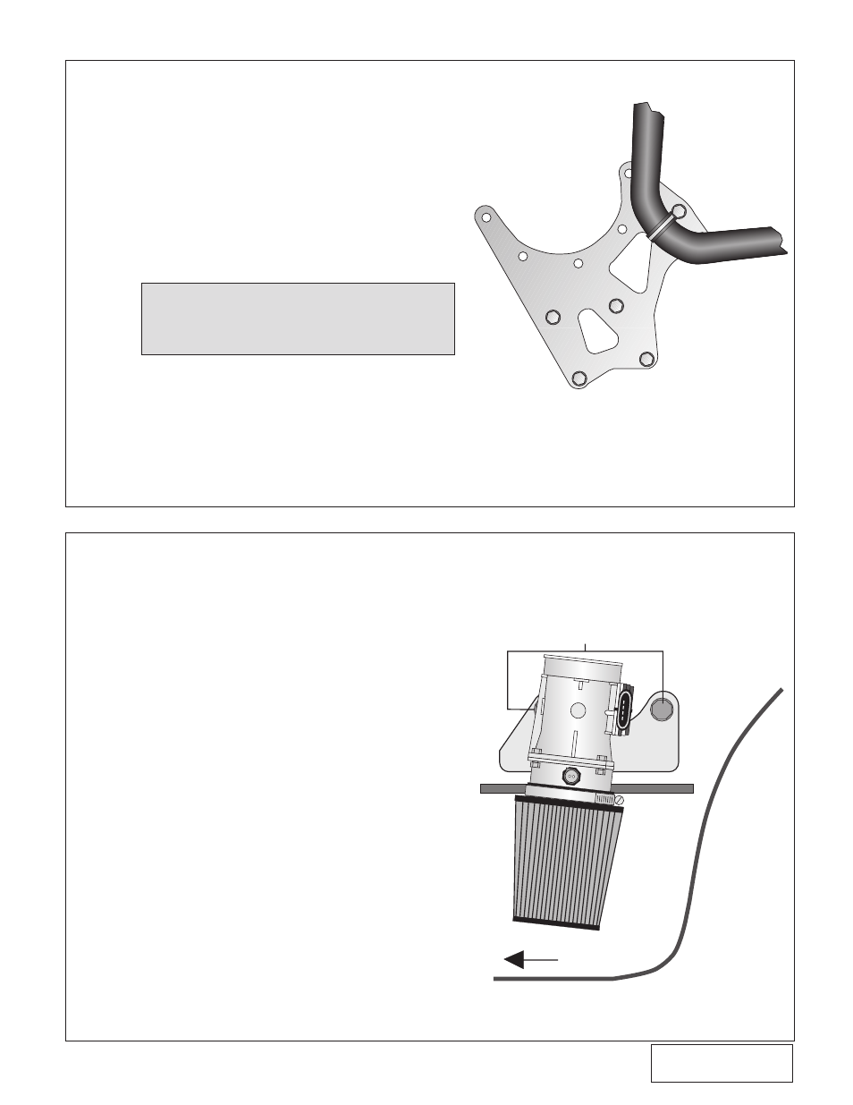
C. Attach the coolant hose to the front supercharger
mounting plate using the supplied #15 adel clamp
and the 3/8" bolt as shown in the graphic. Install
coolant hose and clamp onto the water pump
fitting. Trim if necessary.
D. Reconnect the spark plug wires to the distributor.
Carefully rotate the temperature sender to allow
as much clearance for the alternator as possible,
reconnect the temperature sensor plug.
12. MASS AIR FLOW SENSOR RELOCATION
A. Remove the mass air flow (MAF) sensor and
air temperature connector loom from the main
harness.
B. Cut the air temperature sensor wires 3" to 4"
away from the air temperature connector. Us-
ing the supplied wiring, solder wire extensions
(make sure the color of the wires match the
main harness wire colors) to the cut harness.
Slip two of the supplied one inch shrink sleeves
onto each of the cut wires.
C. Reattach the air temperature sensor connector
by soldering it to the extended harness. Posi-
tion the shrink sleeve sections over each of the
solder joints. Gently heat until the tube seals the
joint.
D. Cover the wire assembly with the 18" flex
loom.
E. Remove the two 1/4-20 washers and nuts from
the right lower fender valance and mount the
MAF bracket on the existing studs using the
same washers and nuts to fasten to the inner
fender. (See Fig. 12-a.)
NOTE: Make sure that the hoses are routed smoothly
with no kinks or sharp bends and away from
all heat sources.
11. COOLANT HOSE REROUTING AND ENGINE COMPONENT REASSEMBLY
Fig. 11-a
1/4-20 NUTS AND WASHERS
INSIDE
RIGHT FRONT
PASSENGER
FENDERWELL
FRONT
Fig. 12-a