Vortech 1996-1998 Ford 4.6L Mustang Cobra User Manual
Page 24
P/N: 4FK020-010
©2008 Vortech Engineering, LLC.
All Rights Reserved, Intl. Copr. Secured
24NOV08 v3.0(4.6L DOHC Cobra (4FK v3.0))
14
(Steps 7-M thru 7-P apply to 1996-1997
models only)
M. Attach the previously removed diverter valve
to the supplied diverter valve support using
the original hardware. Using the supplied
5/16” x 3/4” bolt and previously installed 8mm
x 70mm bolt, attach valve assembly to the alu-
minum supercharger bracket (see Fig. 7-i).
N. Use the supplied 3/4” x 90° rubber hose to
reconnect the valve to the plastic TEE. Trim
as necessary.
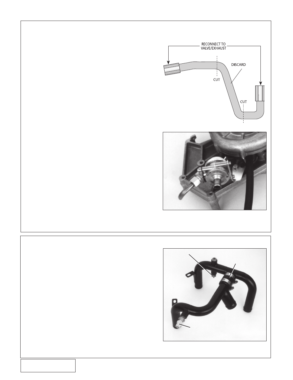
O. The original diverter valve to exhaust manifold
tube must be modified. Cut the tube and de-
burr as shown in Fig. 7-h, and reconnect each
flared end to its original locations (exhaust and
valve). Using the supplied 1/2” piece of “high
heat” rubber hose and two #8 hose clamps,
connect the two ends on the modified steel
tube together. Trim hose if necessary.
P. Remove the small 90° rubber end on the fac-
tory plastic vacuum hose originally connected
to the diverter valve. Using the supplied piece
of 5/32” x 4 foot vacuum hose, connect the
diverter valve, in its new location, to the hard
plastic vacuum hose originally used. Cut the
piece of rubber 5/32” hose to proper length
and set aside the remaining portion for use
later on the supercharger air bypass valve.
Q. Reinstall the factory coolant reservoir and
secure.
8. RADIATOR HOSE/WATER TUBE
A. Remove the upper radiator hose from the radiator
and modify (cut) as shown in Fig. 8-c on page
16.
B. With the lower radiator hose still connected to
the radiator, remove 2” from the end previously
connected to the factory water tube. Set the 2”
section aside.
C. Following Fig. 8-d on page 16, pre-
assemble the Vortech supplied “L” and “U” bend
water tubes using the 2” hose section removed
in point 8-B and the supplied #20 clamps. (Do
not tighten clamps until assembly is mounted
on the engine.)
7. MAIN BRACKET ASSEMBLY/DRIVE BELT, cont’d.
1996 - 1997 moDElS only
Fig. 7-i
SinglE poSt SEnSor
2” hoSE SEction
From loWEr raDia-
tor hoSE
plaStic connEctor EnD
Fig. 8-a
Fig. 7-h