Vortech 1996-1998 Ford 4.6L Mustang Cobra User Manual
Page 13
P/N: 4FK020-010
©2008 Vortech Engineering, LLC.
All Rights Reserved, Intl. Copr. Secured
24NOV08 v3.0(4.6L DOHC Cobra (4FK v3.0))
3
4. FUEL MANAGEMENT UNIT
A. Position the FMU onto the passenger’s side in-
ner fender and secure with the supplied sheet
metal screws (see Fig. 4-a on page 4).
B. Disconnect and discard the factory rubber fuel
return line running from the fuel rail (NOTE: the
return line DOES NOT have a pressure test fitting
on it) to the steel return line (the smaller of the
two) located behind the right side shock tower
using a spring lock disconnect tool.
C. Connect the FMU inlet hose (the hose that goes
to the 90° fitting on the side of the FMU) to the
return side of the factory fuel regulator on the
fuel rail. (See Fig. 4-b on page 4.)
D. Connect the FMU outlet hose (attaches to the
center fitting on the bottom of the unit) to the
steel return line running to the tank. Make sure
hose end is securely “snapped” onto factory fuel
return line.
E. Secure the fuel lines away from abrasion and
exhaust heat with the tie wraps provided.
F. Attach the supplied length of 5/32” vacuum
hose to the fitting on top of the FMU. Connect
the opposite end of the hose to the factory fuel
regulator vacuum connection using the 5/32”
TEE provided. Trim hose length as necessary.
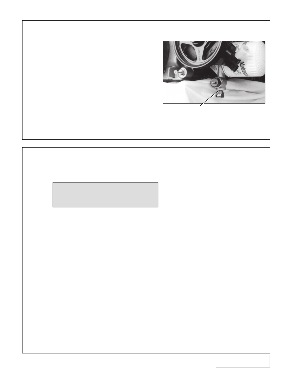
A. Remove the 1/4” NPT socket head plug located
perpendicular to and directly beneath the factory
oil pressure sending unit. This is found on the
engine’s left side below the oil filter.
B. Thread the supplied 1/4” NPT #4 flare x 90° fit-
ting into the pressure sending unit mount using
engine oil on the pipe threads (see Fig. 3-a).
Teflon tape or other sealants are not recom-
mended as it might loosen and cause blockage
of the oil feed orifice, resulting in supercharger
failure. Rotate the fitting so that the flare points
toward the front of the vehicle.
C. Temporarily cap off the flare fitting to prevent dirt
from entering. The oil feed will be connected at
a later time.
1/4” npt x 90° Fitting
Fig. 3-a
NOTE: If a Vortech Power Cooler is being
installed at the same time as the su-
percharger system, refer to the Power
Cooler Installation Manual for the proper
FMU mounting location.
3. OIL FEED (ENGINE OIL-FED APPLICATIONS ONLY. APPLICATIONS WITH V-3
SUPERCHARGERS SKIP AHEAD TO STEP 4)