Main bracket assembly – Vortech Ford Driver's Side Renegade System User Manual
Page 9
P/N: 007062
©2003 Vortech Engineering, LLC
All Rights Reserved, Intl. Copr. Secured
28JAN03 v2.0
(DS Rngde S/C Sys(7062 v2.0))
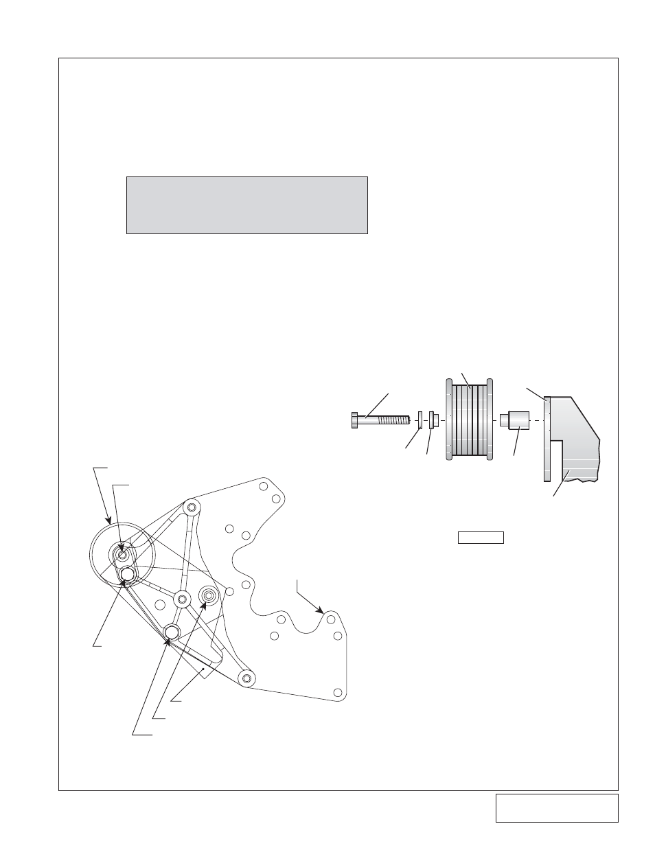
5. MAIN BRACKET ASSEMBLY
A. Attach the cast aluminum bracket and billet
aluminum "3-hole" spacer (the spacer must be
between the bracket and cylinder head) to the
front of the driver side (left) cylinder head using
the supplied 7/16-14 socket-head bolt without
washer. Install the bolt finger tight only (see
Fig.
5-a).
B. Match the mounting plate up to the mounting
bracket and finish attaching the assembly to the
head using the supplied hardware as shown in
Fig. 5-a (make sure that all bolts use the proper
AN washer except the socket-head bolt).
C. Following
Fig. 5-b, attach the idler pulley to the
plate and bracket using the 3/8 x 2-1/2" bolt,
bearing pilot and spacer. Tighten all fasteners in
a progressive manner.
NOTE
: The largest hole (5/8-11) in the end of the
cylinder head MUST have the factory Ford
adapter plug to allow proper hardware fit.
3
Fig. 5-a
Fig. 5-b
GROOVED IDLER PULLEY WITH SPACER & PILOT
(ON TOP OF MOUNTING PLATE)
7/16-14 x
7-1/2 HEX HD
w/WASHER
3/8-16 x 2 1/2 HX HD
7/16-14 X 7 1/2 HEX HD w/WASHER
7/16-14 X 3 SOC. HD.
(THROUGH BRACKET CASTING ONLY)
S/C MOUNTING PLATE
(ON TOP OF MOUNTING
BRACKET)
LEFT SIDE CYLINDER HEAD
ACCESSORY IDLER ASSEMBLY
SIDE VIEW
3/8” AN
WASHER
PILOT
IDLER
SPACER
3/8-16 x 2-1/2” BOLT
SUPERCHARGER
MOUNTING
PLATE
SUPERCHARGER
MOUNTING BRACKET
GROOVED
ACCESSORY