Replacing a power supply module – StorCase Technology DS550 User Manual
Page 37
DS550 User's Guide - Rev. A04
StorCase Technology, Inc.
Appendix B - Optional Accessories
29
Replacing a Power Supply Module
The DS550 comes equipped with two (2) auto-ranging power supply modules. This allows
the DS550 chassis to run in Shared Mode, thus enabling both power supplies to operate at
a reduced wattage and lower operating temperature. If one power supply module should fail,
the other will carry the full load without interruption.
Should a blower slow down or fail, a red indicator light on the front panel will flash.
Blower Error Indicator
The user must visually inspect the Status LEDs located on each power supply module (refer to
section "DS550 Rear Panel" in the Introduction of this User's Guide for further information) to
determine which blower is faulty.
NOTES: The power supply modules are hot-swappable. The DS550 may remain ON when
removing and installing a power supply module.
If module slot is to be left empty, the filler plate (provided) must be installed. Installation
of the filler panel is necessary for proper cooling inside chassis.
In the event a blower fails, always set the speed of the remaining blower to High.
The error light will reset automatically when faulty module is replaced.
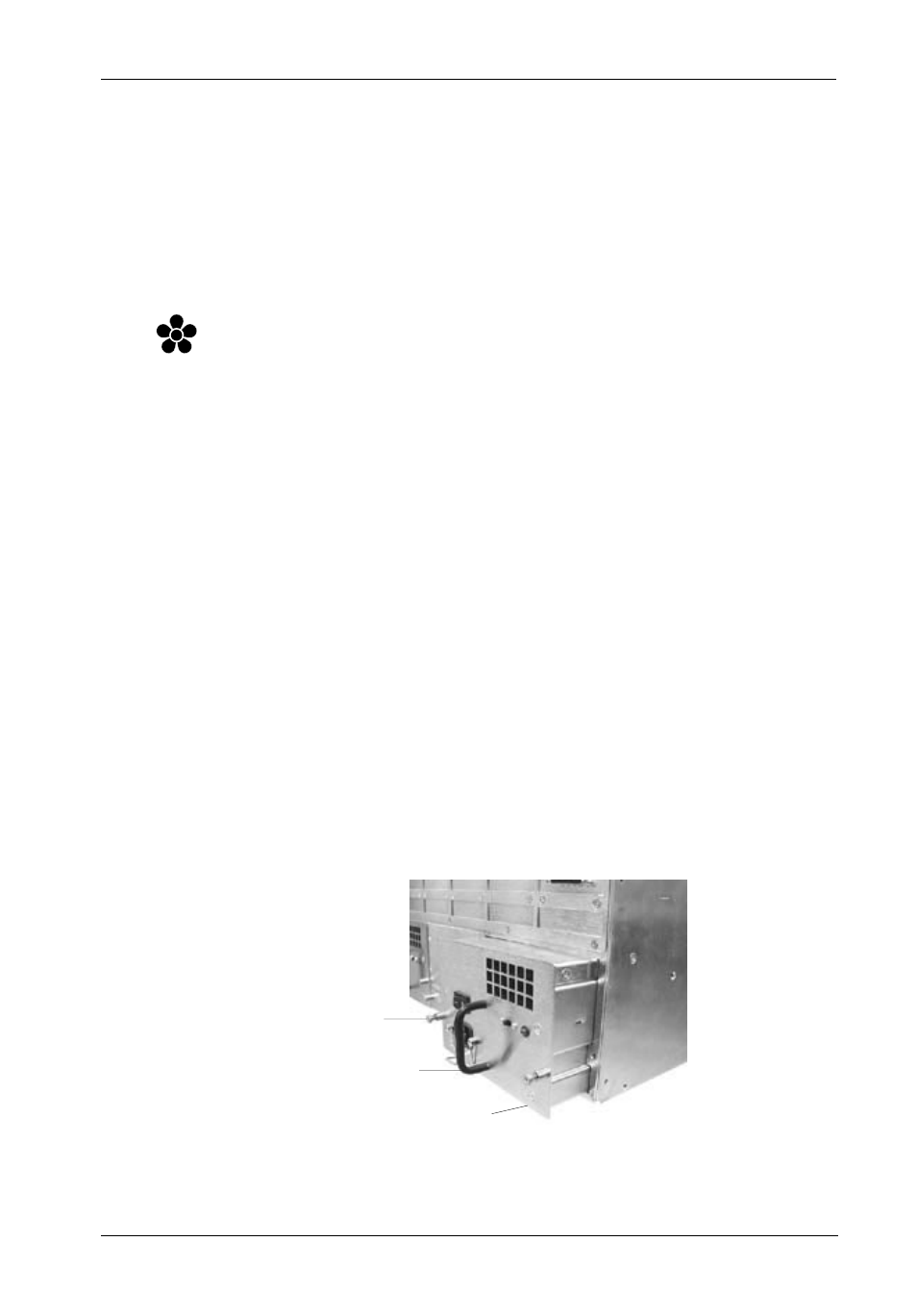
1.
To remove the power supply module to be replaced, simply loosen both captive
screws and slide the module out (Figure B-10).
2.
Insert new module and tighten both captive screws.
3.
Install the A/C power cord and turn ON power.
Figure B-10: Removing/Installing the Power Supply Module
Power Supply
Module
Module
Handle
Captive Screw
(2 per Module)
550_1