Figure 11: installing the drive – StorCase Technology DS500 User Manual
Page 20
12
Installation
StorCase Technology, Inc.
DS500 User's Guide - Rev. E00
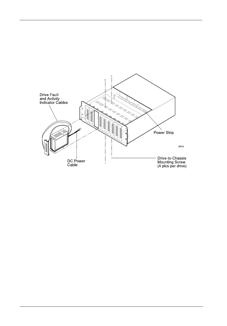
Figure 11: Installing the Drive
NOTE: The DS500 is equipped with a removable drive bay partition located on the front
panel of the DS500 (Figure 2). This partition may be removed so that drives can
be spaced apart for increased chassis ventilation.
5. Reinstall the filler panel(s) that were removed earlier (fixed media devices only). Check
the clearance between the newly installed drive(s) and the filler panel(s). If installing
removable media devices, verify that the installed devices are flush with the DS500
front panel.
6. Tighten the drive mounting screws.
7. Connect the SCSI I/O cable(s) to the drive(s). Verify that the Pin 1 indicator on the cable
is properly aligned (Figure 12 ). Refer to the drive manufacturer's documentation for
specific drive information. StorCase offers several internal SCSI cable configurations
for the DS500 (refer to Appendix B for available internal SCSI cables).
8. Connect the 4-pin DC power cable(s) from the device to the Data Silo power strip
(Figure 8).
9. Reinstall the Data Silo cover and fasten all screws.
10. Connect the external A/C power cable to the Data Silo.
3. Attach the drive activity and drive fault indicator LED cables to the appropriate drive
pins (refer to the device manufacturer's documentation for the location of these pins).
4. Install the drive(s) into the drive mounting bracket using four (4) #6-32 x 1/4" screws
(Figure 11). Be careful not to pinch or crimp attached cables. Do not fully tighten
the screws at this point.