Drive installation, Figure 10: removing the filler panel – StorCase Technology DS500 User Manual
Page 19
Installation
11
DS500 User's Guide - Rev. E00
StorCase Technology, Inc.
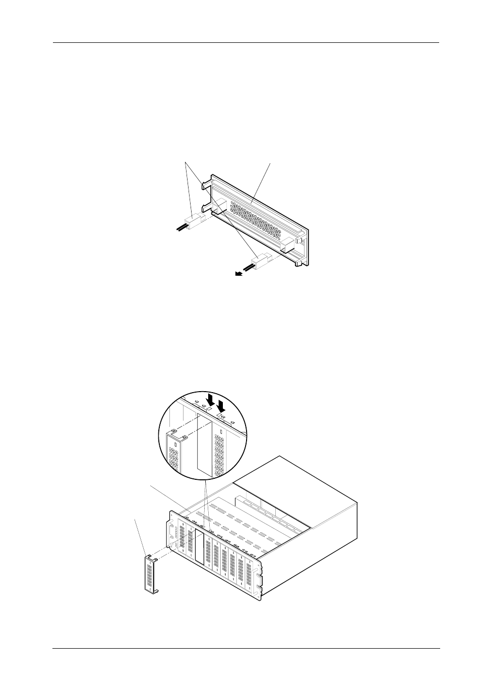
Device Filler Panel
(back side)
Flat Side of Connector
Faces Up
0581
To 2mm Device
Connector
Figure 9: Installing the LEDs into the Filler Panel
0247
Press in these Cutouts
to Remove the
Appropriate Filler Panel
Drive Filler
Panel
Drive Mounting
Bracket
Figure 10: Removing the Filler Panel
2. For front-loading devices: Remove the appropriate filler panels from the DS500.
Apply a small amount of pressure with the tip of a flat blade screwdriver to the filler
panel clips located on the side of the drive mounting bracket (Figure 10).
Drive Installation
1. For fixed media devices: Install the drive activity and drive fault LEDs into the
appropriate front filler panels. Gently push each LED into the rear of the filler panel
as shown in Figure 9 below.
- DE100i-SW (35 pages)
- DE110 (27 pages)
- DE50 (33 pages)
- DE50 (27 pages)
- DE110 (33 pages)
- DE110 (2 pages)
- DE110 (31 pages)
- DX115 (25 pages)
- DE75i-A (31 pages)
- DE75i-A66 (29 pages)
- DE75i-A100 (31 pages)
- SATA DE75 (28 pages)
- DE75i-S (31 pages)
- DE75i-SW (33 pages)
- DE75i-SWC (33 pages)
- DE75i-SW160 (29 pages)
- S20A114 (29 pages)
- DE75i-SWC160 (29 pages)
- DE90i-A (29 pages)
- DE90i-A66 (23 pages)
- DE90i-A100 (23 pages)
- DE90i-S (25 pages)
- DE100i-A (33 pages)
- DE100i-A66 (29 pages)
- DE100i-A100 (29 pages)
- DE100i-CSWTN (2 pages)
- DE100i-S (39 pages)
- DE100i-SWD (33 pages)
- DE100i-SWU2 (37 pages)
- DE100i-SWCU2 (33 pages)
- DE100i-SWU2X (35 pages)
- DE100i-SW160 (35 pages)
- S20A102 (33 pages)
- DE100i-SWC160 (39 pages)
- Ultra320 DE100 (31 pages)
- DE110 (29 pages)
- DE110 (27 pages)
- DE110 (31 pages)
- DE150i-SWC (33 pages)
- DE200i-S (33 pages)
- DE200i-CSWTN (2 pages)
- DE200i-SW (35 pages)
- DE200i-SWU2 (37 pages)
- DE200i-SWCU2 (35 pages)
- S20A108 (33 pages)