Installing the replacement power supply – StorCase Technology DS400 User Manual
Page 35
26
Appendix B - Optional Accessories
StorCase Technology, Inc.
DS400 User's Guide - Rev. E01
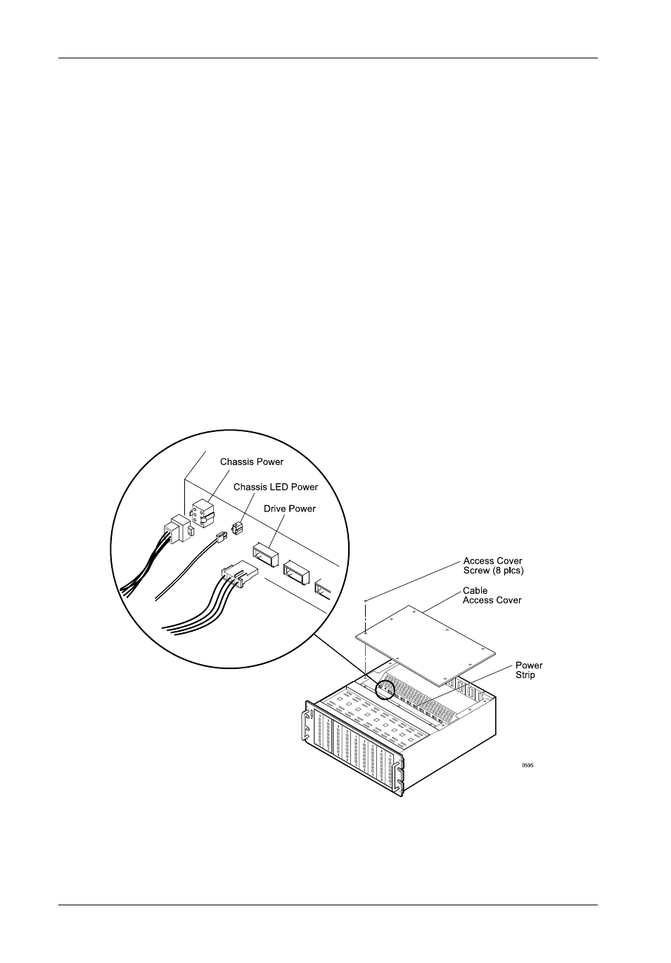
Figure B-8: Removing the Cable Access Cover/Disconnecting
the Internal Cables
Installing the Replacement Power Supply
A power supply LED indicator is located on DS400 back panel (Figure C-8). When illuminated,
this LED indicates that the power supply is functioning normally. If this indicator fails to illuminate
when the chassis power is on, it is an indication that a problem with the power supply has
occurred. If this is the case, replace the power supply module.
A diagnostic connector (3.00mm Molex - P/N 43020) located on the DS400 back panel, provides
system operating status. A 4.5 to 5V reading indicates normal operating status. A reading
below 4.5 to 5V indicates a system malfunction.
Follow the steps below to replace the DS400 power supply.
CAUTION:
Disconnect all power from the DS400 before opening the chassis.
1. Verify that all power is off and that the cables have been disconnected from the DS400
chassis.
2. Remove the cable access cover as shown in Figure B-8.