Front panel – StorCase Technology DS400 User Manual
Page 13
4
Introduction
StorCase Technology, Inc.
DS400 User's Guide - Rev. E01
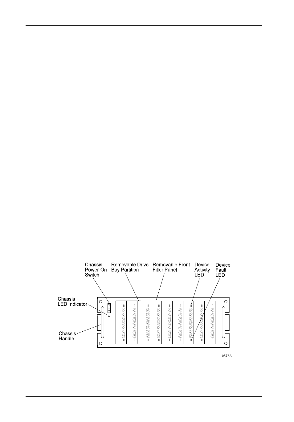
Figure 3: DS400 Front Panel
Front Panel
(Figure 3)
Chassis Power-On Switch - Front-mounted rocker switch controls power to the
chassis.
Removable Drive Bay Partition - Removing this partition allows drives to be spaced
apart for additional chassis ventilation.
Removable Filler Panel - Accommodates removable media devices (e.g. CD-ROM,
DAT drives, etc).
Device Activity LED - Provides a visual indication of drive activity. This LED is housed
in the removable filler panel(s) and provides connectors which can easily be attached
to the installed drive(s) within the chassis.
Device Fault LED - Provides a visual indication of the status for each installed drive.
This LED is housed in the removable filler panel(s) and provides connectors which
can easily be attached to the installed drive(s) within the chassis.
Chassis LED/Audio Indicator - Provides the following operating information:
· Green
= Power On
· Red
= Fan Failure
· Flash Red = Chassis Temperature Exceeds 40°C
(Power to drives cut off at 50°C)
Chassis Handle - Provides a sturdy grip for the installation and removal of the rack
mount chassis.