Unit id select switch settings, Figure 11: unit id select switch location, Drive selection – StorCase Technology DE100i-A User Manual
Page 22: Led number display, Master slave master slave blank, Blank blank, Blank blank blank
DE100i-A User's Guide - Rev. F01
StorCase Technology, Inc.
Installation
15
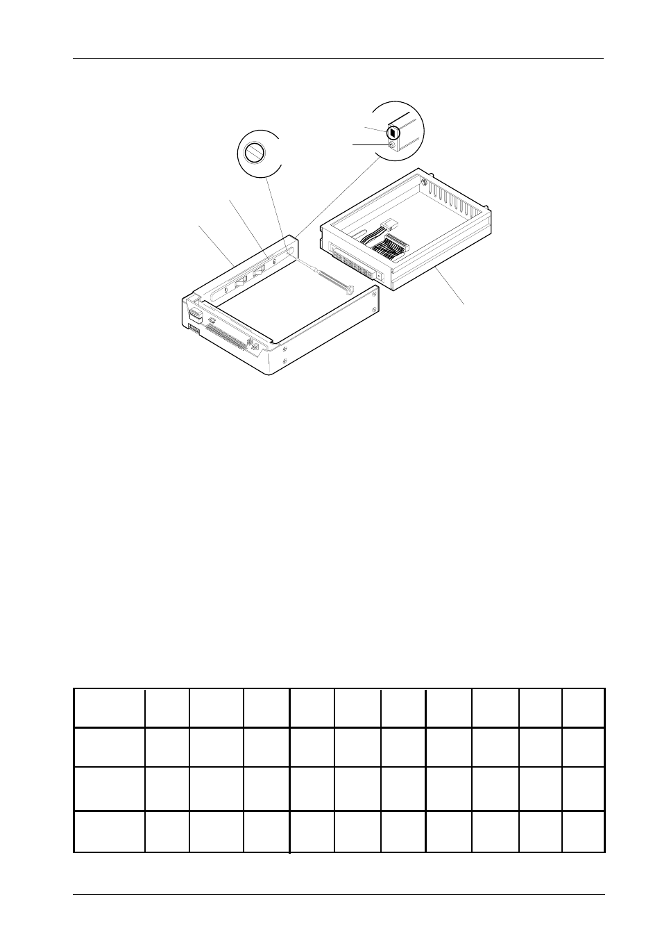
Drive Carrier
Guide
Receiving
Frame
Unit ID Select
Rotating Switch
Drive Carrier
(removed)
Unit ID
Number
Display
Lock
and DC
Power
Switch
Front of Unit
0087
Figure 11: Unit ID Select Switch Location
Unit ID Select Switch Settings
The following table lists the Unit ID Select Switch settings and the valid AT/IDE unit numbers.
Please note that all invalid switch settings have shaded boxes and result in a blank display
in the receiving frame display window.
Table 3: Unit ID Select Switch Settings
Unit Select
Position
0
1
2
3
4
5
6
7
8
9
AT/IDE
Drive
1
2
1
2
LED Number
Display
Drive
Selection
1234567890
1234567890
1234567890
1234567890
1234567890
1234567890
1234567890
1234567890
123456789012345678
123456789012345678
123456789012345678
123456789012345678
123456789012345678
123456789012345678
123456789012345678
123456789012345678
12345678901234567890123456
12345678901234567890123456
12345678901234567890123456
12345678901234567890123456
12345678901234567890123456
12345678901234567890123456
12345678901234567890123456
12345678901234567890123456
123456789012345678
123456789012345678
123456789012345678
123456789012345678
123456789012345678
123456789012345678
123456789012345678
123456789012345678
12345678901234567890123456
12345678901234567890123456
12345678901234567890123456
12345678901234567890123456
12345678901234567890123456
12345678901234567890123456
12345678901234567890123456
12345678901234567890123456
1234567890
1234567890
1234567890
1234567890
1234567890
1234567890
1234567890
1234567890
Master Slave Master Slave
Blank
0 1
Blank Blank
2 3
Blank Blank Blank