StorCase Technology DE100i-A User Manual
Page 14
DE100i-A User's Guide - Rev. F01
StorCase Technology, Inc.
Installation
7
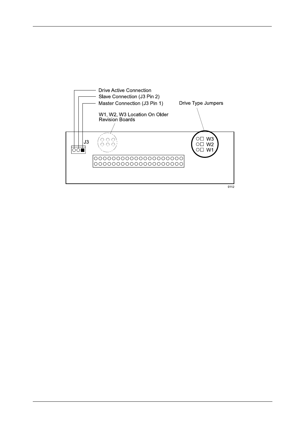
and drive activity indicator light. A 3-pin wire-wrap connector is provided to enable you to
fabricate a cable (cable not included) from the AT/IDE drive to the DE100i-A carrier circuit
board. Figure 6 illustrates the Drive Carrier Circuit Board.
Figure 6: DE100i-A Drive Carrier Circuit Board
The J3 connector has three (3) pins:
J3 Pin 1
should be connected to the Master signal of the disk drive. This signal
indicates that this is the Master C: drive.
J3 Pin 2
should be connected to the Slave/Slave Present signal of the drive. This
signal indicates whether a Slave D: drive is present or not.
J3 Pin 3
may optionally be connected to the "Active" signal of the drive. This signal
controls the level of the drive activity indicator light on the front panel of the
receiving frame. The receiving frame circuit board is designed to route the
drive's -HOST SLV/ACT signal (drive activity) to the activity indicator light on
the front panel of the Data Express receiving frame. A connection to J3 Pin
3 (on the carrier board) should only be made if the drive does not support
this -HOST SLV/ACT signal on Pin 39 of the interface connector (check the
documentation that accompanied the drive and controller). If the J3 Pin 3
connection is made, move jumper JP39 on the receiving frame rear panel from
the "A" position to the "B" position.
Three Drive Type Jumpers, W1, W2, and W3 are available to control the signal levels at J3,
Pins 1 & 2.