StorCase Technology DE100i-A User Manual
Page 17
10
Installation
StorCase Technology, Inc.
DE100i-A User's Guide - Rev. F01
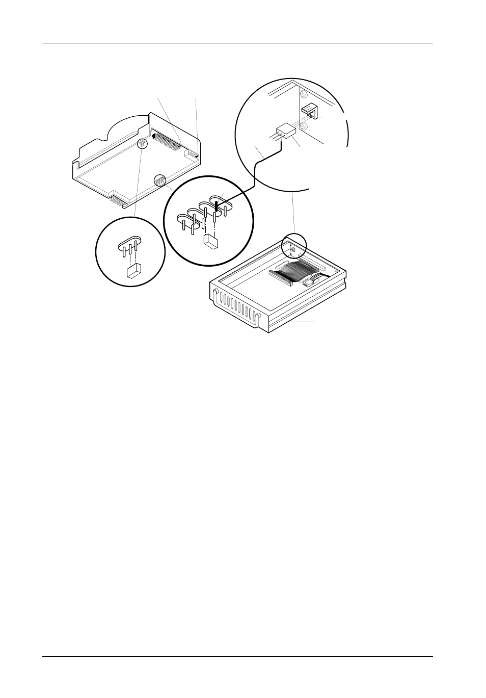
J4, Pin 1
Power
Connector
J2, Pin 1
AT/IDE
Interface
J3 Pin1
E1
E2
E3
C/D
SS
DSP
116
J3 Pin 1
Required
Jumper
Wire
Drive Carrier
3-PIN WIRE WRAP CONNECTOR
(Provided). Used for fabricating a single
wire connection (wire not provided)
between the drive and J3 Pin-1 on the
drive carrier circuit board.
Figure 7: Typical AT/IDE Drive Connections
Typical AT/IDE drive jumper positions are shown in Figure 7. Remove and save all the jumpers.
Install a wire (not provided) from the C/D pin to the connector provided with the DE100i-A:
C/D
The darkened pin in the figure above is connected to Pin 1 of the provided wire
wrap connector.
DSP Install the jumper in the DSP position as shown in Figure 7.
Install the wire wrap connector onto J3 on the drive carrier circuit board.
NOTE:
Install jumpers W1 and W2 on the DE100i-A drive carrier circuit board, and remove
the W3 jumper as shown in Table 1.
- DE100i-SW (35 pages)
- DE110 (2 pages)
- DE110 (31 pages)
- DE110 (27 pages)
- DE50 (33 pages)
- DE50 (27 pages)
- DE110 (33 pages)
- DX115 (25 pages)
- DE75i-A (31 pages)
- DE75i-A66 (29 pages)
- DE75i-A100 (31 pages)
- SATA DE75 (28 pages)
- DE75i-S (31 pages)
- DE75i-SW (33 pages)
- DE75i-SWC (33 pages)
- DE75i-SW160 (29 pages)
- S20A114 (29 pages)
- DE75i-SWC160 (29 pages)
- DE90i-A (29 pages)
- DE90i-A66 (23 pages)
- DE90i-A100 (23 pages)
- DE90i-S (25 pages)
- DE100i-A66 (29 pages)
- DE100i-A100 (29 pages)
- DE100i-CSWTN (2 pages)
- DE100i-S (39 pages)
- DE100i-SWD (33 pages)
- DE100i-SWU2 (37 pages)
- DE100i-SWCU2 (33 pages)
- DE100i-SWU2X (35 pages)
- DE100i-SW160 (35 pages)
- S20A102 (33 pages)
- DE100i-SWC160 (39 pages)
- Ultra320 DE100 (31 pages)
- DE110 (27 pages)
- DE110 (31 pages)
- DE110 (29 pages)
- DE150i-SWC (33 pages)
- DE200i-S (33 pages)
- DE200i-CSWTN (2 pages)
- DE200i-SW (35 pages)
- DE200i-SWU2 (37 pages)
- DE200i-SWCU2 (35 pages)
- S20A108 (33 pages)