StorCase Technology DE100i-A User Manual
Page 20
DE100i-A User's Guide - Rev. F01
StorCase Technology, Inc.
Installation
13
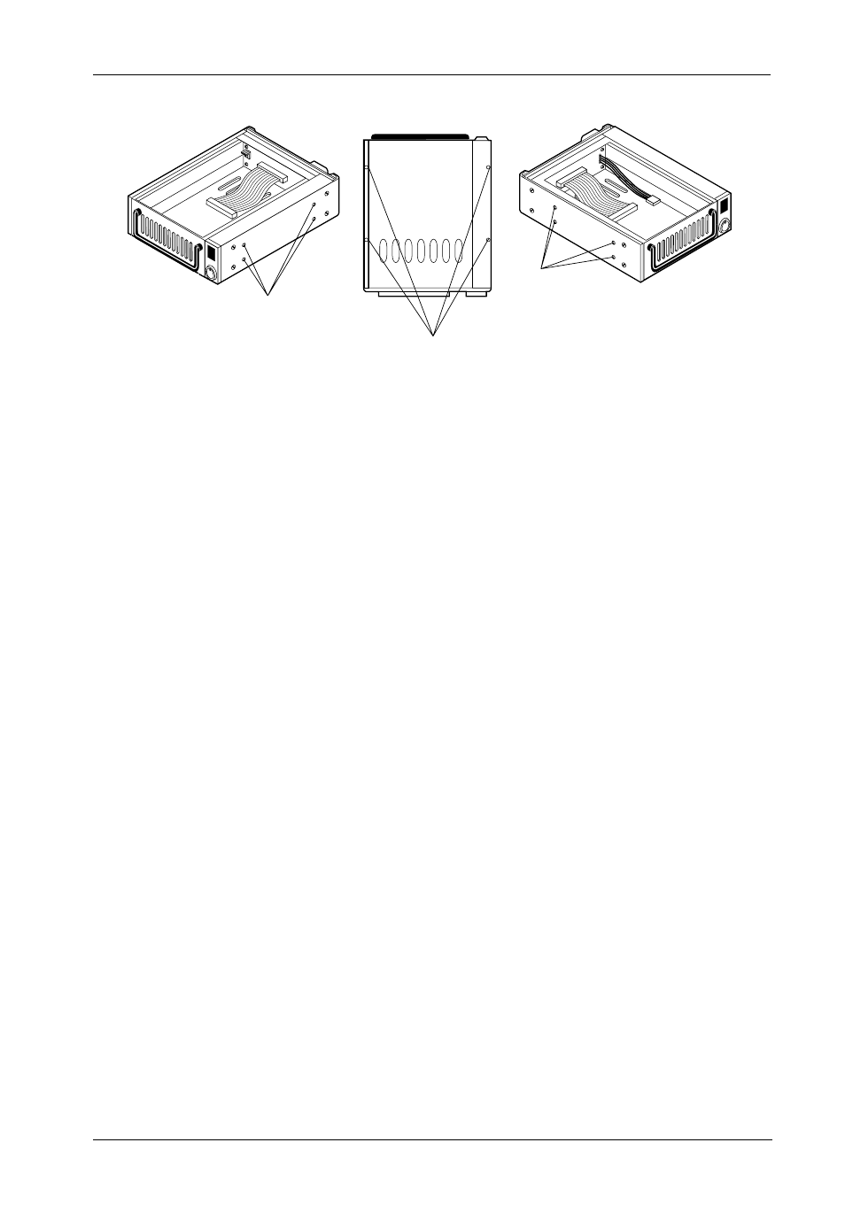
Mounting
Holes (Right)
Mounting
Holes (Bottom)
Front of Unit
Mounting
Holes (Left)
0086
Figure 10: Receiving Frame Mounting Holes
6. To connect the drive to a Remote Activity LED in the computer system connect
the appropriate cable(s) to the receiving frame rear panel as shown in Figure
5. Connect J7 Pins "A" & "C" to a remote activity LED.
7.
Connect the I/O cable from the host adapter to the receiving frame. The Pin 1
indicator on the cable must be properly aligned. Refer to Figure 5 for the correct
Pin 1 location.
8.
Connect the power cable from the DC power supply in the computer or expansion
chassis to the power connector on the DE100i-A receiving frame. Refer to
Figure 5 for the DE100i-A receiving frame power connector location.
9.
Replace any expansion boards that may have been removed earlier. Replace
the system cover according to the manufacturers instructions.
10.
Reconnect any system or peripheral cables removed earlier.
11.
Turn ON power to the computer. If the installation has been successful, and all
the cables have been properly attached, the system should boot normally.
Although the computer may not recognize the DE100i-A yet, the front panel
display on the Data Express should illuminate.
12.
The new drive may need to be formatted or initialized prior to use with the
operating system and applications software. Refer to the drive and/or computer
manufacturer's documentation for formatting information.