StorCase Technology DE90i-S User Manual
Page 14
DE90i-S, Rev. A00
Kingston Technology Company
Installation
9
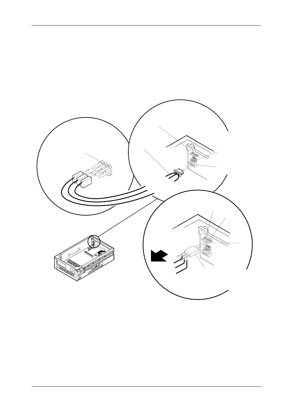
Figure 5 illustrates a typical SCSI ID select connection to a drive with 2mm ID select pins.
Attach the ID select cable to the drive using the 2mm connectors. Align the “ID0” pin with the
black wire. Attach the 1.25mm connector on the other end of the ID select cable to the
1.25mm connector (J3B) provided on the signal distribution board, located inside the carrier.
Refer to the manufacturer’s documentation to disable termination on the drive.
Figure 5 : Typical SCSI ID Select Connections (2mm Drive Pins)
0412
Signal Distribution
Board
ID
Select
Cable
Red (ID2)
Brown (ID1)
Black (ID0)
DISK DRIVE
CARRIER
BOARD
K
ingston
Data
Expr
ess
Typical 2mm Drive ID Select Pins
(Pins vary on each drive model. See
Drive Manufacturer's Information.)
1.25mm Data
Express ID Select
Interface (J3B)
2mm Data Express
ID Select Interface
(J3A)
To Drive ID
Select Pins
To ID0
To ID1
To ID2
3-PIN WIRE WRAP
CONNECTOR (Provided). Use
in place of ID select cable
if there is not enough space.
Connects to J3.
Pin 1
J3
J6
(Reserved)