Installation – StorCase Technology DE90i-S User Manual
Page 13
8
Installation
Kingston Technology Company
DE90i-S, Rev. A00
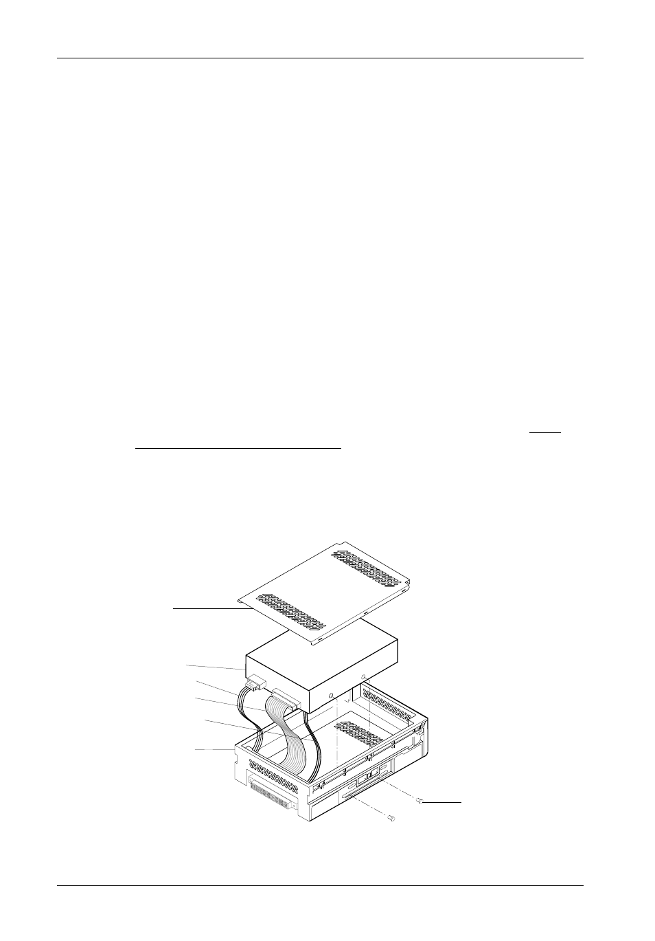
Drive Carrier
Disk Drive
Power Cable
I/O Interface
Cable/s
ID Select Cable
0413
Drive
Cover
(Provided)
Drive Mounting
Screws (4 plcs)
# 6-32 x 1/4"
NOTE:
SCSI units are provided with a single row 3-pin wire wrap connector. This
connector allows fabrication of ID select cable connections for use in
confined areas or for drives which have nonstandard pin configurations. For
example, drives with side mounted ID select pins will require the use of the
wire wrap connector in place of the standard ID select cable. If required,
install the three wire wrap jumpers from the drive ID pins to the ID select
connector located inside the carrier on the signal distribution board. See
Figures 5 and 6 for the location of the ID select interface connector.
Installation
1.
Attach the I/O interface cable from the rear distribution board of the Data
Express carrier to the disk drive (Figure 4).
2.
Attach the four-pin disk power cable from the rear distribution board to the
disk drive (Figure 4).
3.
Install the three-pin ID select cable into the rear signal distribution board
connector. Refer to Figure 5 for a typical 2mm drive pin connection or Figure
6 for a typical 1.25mm drive pin connection.
4.
Carefully insert the drive into the carrier at an angle, cable-end first. Make
sure none of the cables are pinched. Lower the front of the drive carefully into
place. Fasten the drive into the carrier with four of the eight screws provided
as shown in Figure 4.
5.
Snap the provided drive cover into place as shown in Figure 4.
Figure 4: Drive Installation Assembly