Receiving frame rear panel – StorCase Technology DX115 User Manual
Page 13
6
Introduction
StorCase Technology, Inc.
DE110 for Backup User's Guide - Rev. A04
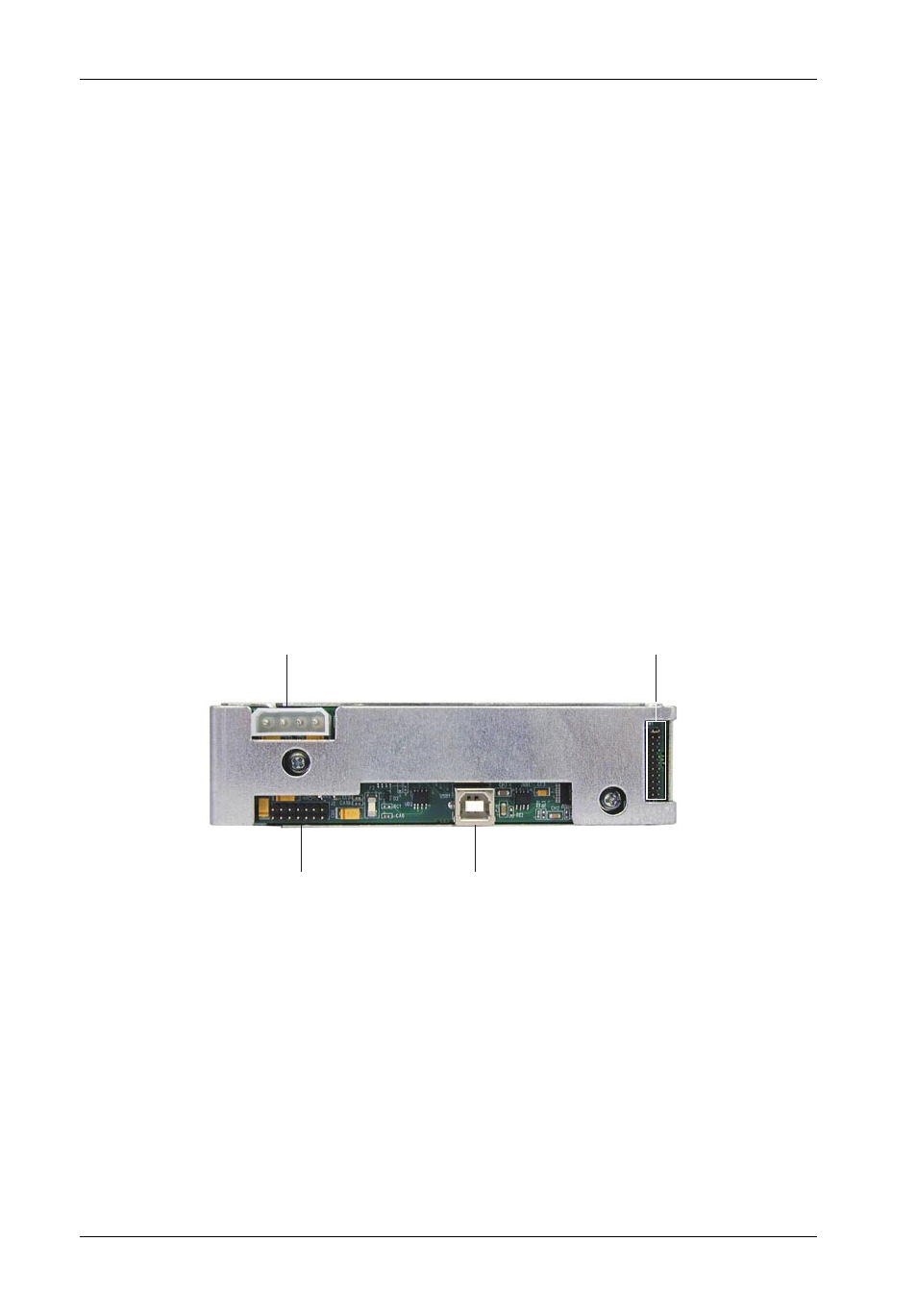
Figure 5A: Receiving Frame Motherboard
(Rear View)
Receiving Frame Rear Panel
(Figures 5A & 5B)
• USB Connector - Provides a standard interface for USB 2.0 signals.
• DC Power Connector (P1) - A standard 4-pin DC power connector is used to accept
DC power.
• Option Pins (W1) - Refer to Figure 5B.
ID0 & ID1 - Jumper is factory-installed on ID0. Change jumper position to Pins 3 & 4 for
ID1 designation. ID0 & ID1 are for ID display purposes only. Refer to Table 1 for further
information.
Remote Activity LED (RLED) - These pins provide power for a remote LED device
activity indicator (Pin 13=Cathode, Pin 14=Anode).
• Factory Reserved Pins - These pins are reserved for factory use only - Do not install
jumper under any circumstances!
USB 2.0
Connector
Option Pin
Connector
Factory Reserved Pins
(No Jumper Installed)
DC Power
Connector