Drive carrier – StorCase Technology DX115 User Manual
Page 12
Introduction
5
DE110 for Backup User's Guide - Rev. A04
StorCase Technology, Inc.
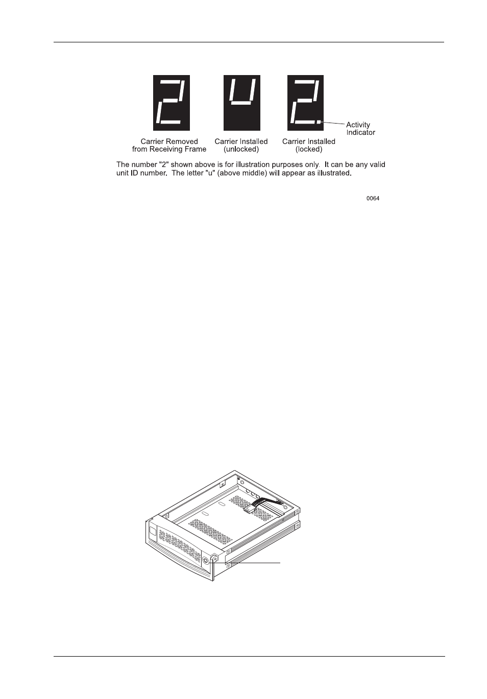
Figure 3B: Receiving Frame Unit ID Number and Activity Display
Drive Carrier
(Figure 4)
• Key Lock/Drive Power Switch (Figure 4) - Performs three functions. The key switch
assures proper seating of the drive carrier within the receiving frame, turns power to
the drive carrier ON and OFF, and prevents unauthorized removal or installation of the
carrier. For the computer to access data on the disk drive, the key must be turned
counterclockwise to the locked position.
NOTE:
Disable USB device on host computer desktop before turning OFF power
(simply right-click on the "Unplug/Eject Hardware" Icon located in the
System Tray and "disconnect").
Key Lock/Drive
Power Switch
0841
Figure 4: Drive Carrier