Receiving frame rear panel – StorCase Technology DE50 User Manual
Page 12
Introduction
5
PATA DE50 User's Guide - Rev. E00
StorCase Technology, Inc.
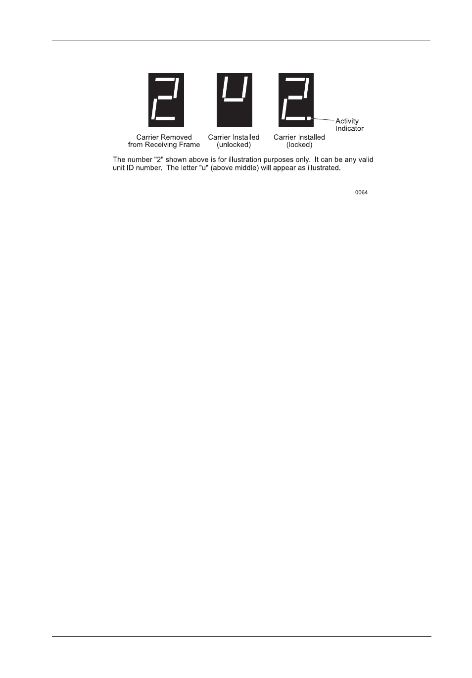
Figure 4: Receiving Frame Unit ID Number and Activity Display
Receiving Frame Rear Panel
(Figure 5)
•
I/O Connector (JP1) - The input/output connector provides a standard interface for
all IDE signals.
•
DC Power Connector (P1) - A standard 4-pin DC power connector is used to accept
DC power.
•
Master/Slave Selection Jumper (J2) - Master Drive configuration (Factory De
fault). Change jumper position to set Slave Drive configuration (Figure 5).
Forces master/slave drive configuration on the receiving frame if JMP1 jumper option
(located on the drive carrier circuit board) is configured to Cable Select (refer to
section "Installation" for further information).
If using the Drive Select Method, this option is instead used to configure the unit ID dis-
play (refer to page 9 for further information).
- DE100i-SW (35 pages)
- DE50 (27 pages)
- DE110 (33 pages)
- DE110 (2 pages)
- DE110 (31 pages)
- DE110 (27 pages)
- DX115 (25 pages)
- DE75i-A (31 pages)
- DE75i-A66 (29 pages)
- DE75i-A100 (31 pages)
- SATA DE75 (28 pages)
- DE75i-S (31 pages)
- DE75i-SW (33 pages)
- DE75i-SWC (33 pages)
- DE75i-SW160 (29 pages)
- S20A114 (29 pages)
- DE75i-SWC160 (29 pages)
- DE90i-A (29 pages)
- DE90i-A66 (23 pages)
- DE90i-A100 (23 pages)
- DE90i-S (25 pages)
- DE100i-A (33 pages)
- DE100i-A66 (29 pages)
- DE100i-A100 (29 pages)
- DE100i-CSWTN (2 pages)
- DE100i-S (39 pages)
- DE100i-SWD (33 pages)
- DE100i-SWU2 (37 pages)
- DE100i-SWCU2 (33 pages)
- DE100i-SWU2X (35 pages)
- DE100i-SW160 (35 pages)
- S20A102 (33 pages)
- DE100i-SWC160 (39 pages)
- Ultra320 DE100 (31 pages)
- DE110 (29 pages)
- DE110 (27 pages)
- DE110 (31 pages)
- DE150i-SWC (33 pages)
- DE200i-S (33 pages)
- DE200i-CSWTN (2 pages)
- DE200i-SW (35 pages)
- DE200i-SWU2 (37 pages)
- DE200i-SWCU2 (35 pages)
- S20A108 (33 pages)