Chapter 6, Accessories – Starrett SR200 Surface Roughness Tester User Manual
Page 27
SR200
Specifications subject to change
6.2
Chapter 6
Accessories
Replacement Standard pick-up (SR-112-1503)
Details as the standard pick-up, (see figure 6 pg 2.5) 10mm (400min) stylus tip radius.
Conforms to US specifications (ANSI B46.1).
Small bore pick-up, 5µm (200µin) stylus tip radius (SR-112-1504)
For general use in small bores, on narrow surfaces and in grooves, or with the skid supported
independently of the surface being measured. On this pick-up the skid is integral with the
stylus arm housing and is set further back from the stylus. This enables the pick-up to be used
in short bores with the skid supported independently of the surface being measured, eg by the
datum support stand.
Figure 9: The small bore pickup
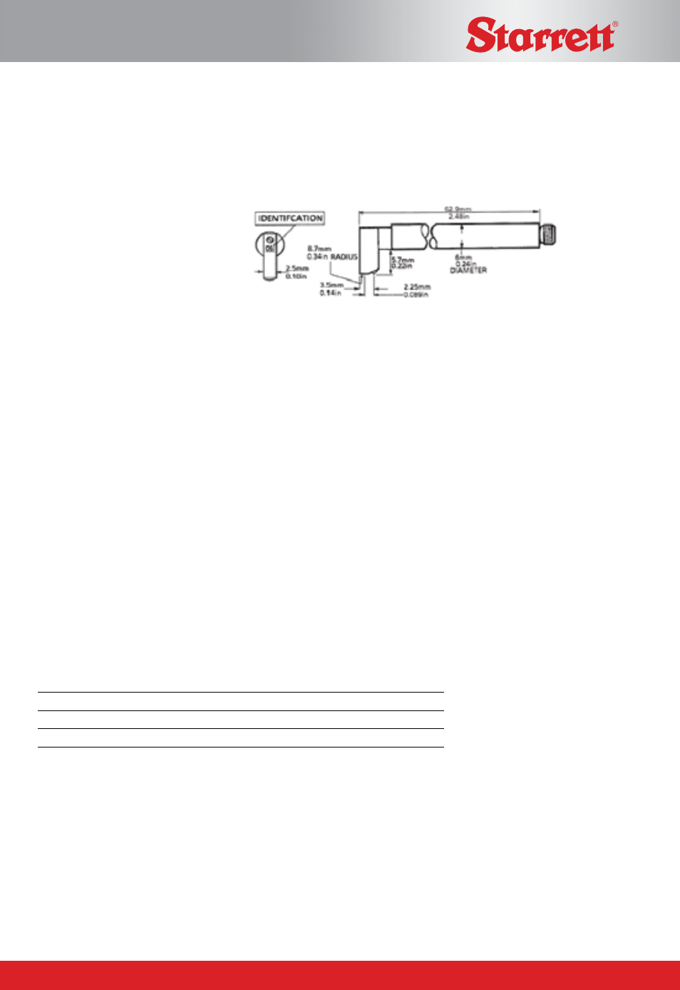
Figure 10: The right angle pickup
Right Angle Pick-up, 5µm (200µin) stylus tip radius (SR-112-1505)
This pick-up is used at right angles to the direction of traverse. Accordingly the skid is set at
right angles to its normal position.
It is particular useful in grooves or slots where the lay of the surface texture makes it unsuitable
for measurement with a standard or small bore pick-up. When used on cylindrical workpieces
it is important that the stylus and skid should be equidistant from the crest (see figure 11), and
that the work piece is positioned so that the crest is parallel to the line of traverse.
Recess pick-up, 5µm (200µin) stylus tip radius (SR-112-1506)
This pick-up has an extended stylus and skid for measuring at the bottom of a recess, or
between shoulders and flanges up to 5.7mm deep. A special deep recess pick-up is available
for measuring up to a depth of 25mm.
Figure 12: The recess pickup
Extension rod (SR-112/1510)
200mm long extension with integral lead, fits between the pick-up and carriage. The extension
rod is fitted to the pick-up in the following manner:
1. Disconnect the pick-up lead from the traverse unit and remove the pick-up from the traverse
unit carriage.
2. Remove the lead from the pick-up
3. Carefully locate the central pin of the extension rod with the hole in the pick-up and screw
the rod and pick-up together.
4. Thread the lead from the extension rod through the hole provided in the back plate of the
traverse unit and connect it to the traverse unit socket.
5. fit the pick-up into the traverse unit carriage, positioned as required.
Power Adaptor
SR-112-3530
Power Adaptor (UK)
SR200
SR-112-3531
Power Adaptor (US-110V)
SR200
SR-112-3532
Power Adaptor (EURO-230V)(2 PIN) SR200