Star Headlight & Lantern DL15-30 User Manual
Page 16
-13-
(Optional TDC850 Controller CONT’D)
TDC850 Option Jumpers
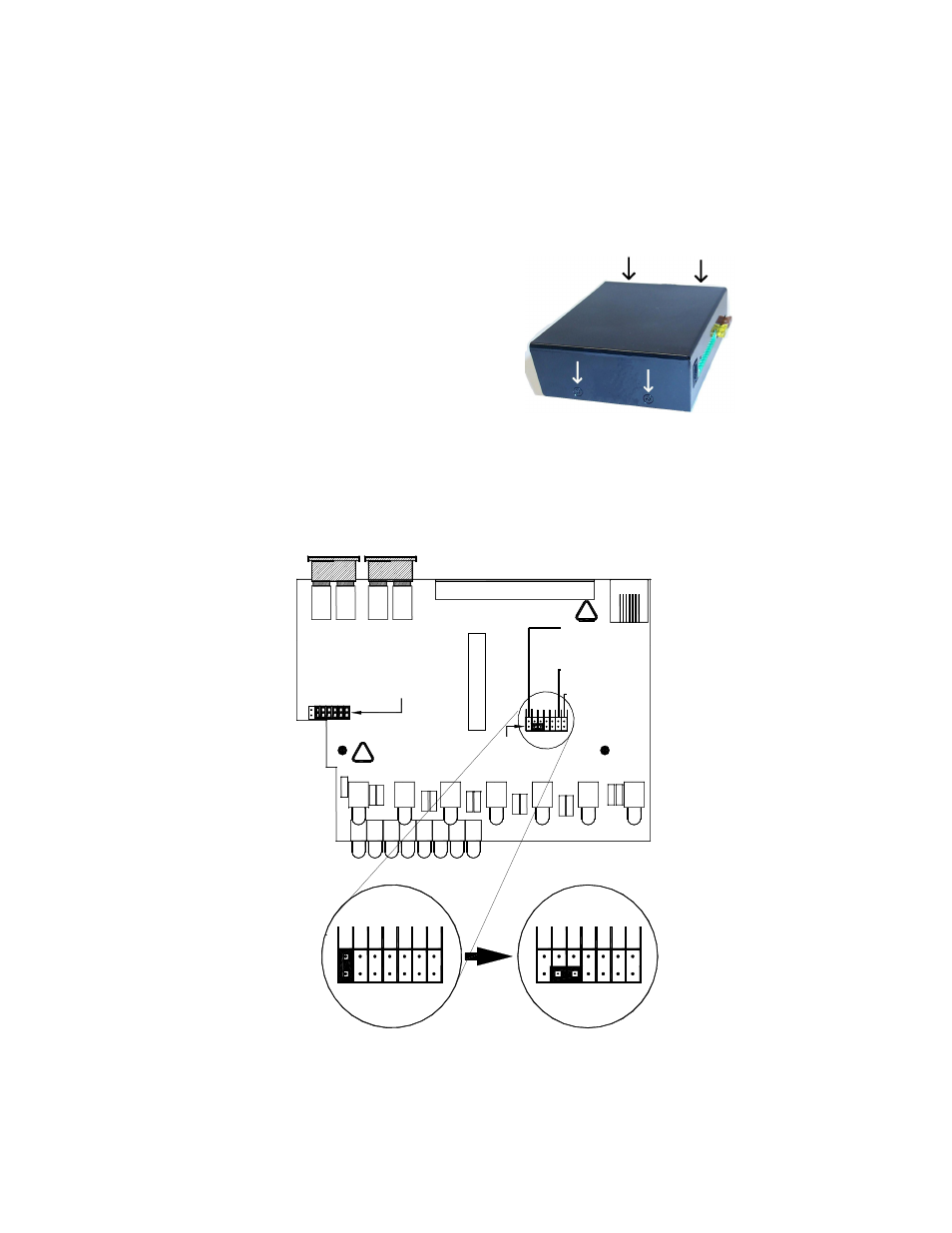
TDC850 Control Box Cover Removal
1. Remove the four recessed Philip head screws
(two on each side of the arrow stick control box).
2. Remove the top cover by sliding it towards the
front of the unit.
3. Locate the extra jumper location near the fuses. Also find the “Option” jumper location
near the center of the board. (See diagram below).
4. There are seven jumpers located inside the TDC850 that can control different options.
By default six of the jumpers are located on the Extra Jumper pins.
5. The 7
th
jumper will be in the “Phantom Mode” position over the 1
st
pair of jumpers.
Remove this jumper from the 1
st
pair of pins and place it over the bottom pins of the 2
nd
and 3
rd
pair of pins as pictured below.
Extra Jumper Locations
Remove the jumper on the 1st pair of pins
and turn it sideways over the bottom row of
the 2nd and 3rd pair of pins (as pictured
here) for DL15-30W Traffic Directing Mode
Control Wires
switched by Ground
Pattern Select wires
controlled by +12VDC
TDC850 Controller (DL15-30W Mode)
Phantom Mode (REMOVE
THE JUMPER FROM
THIS PAIR!!!)
!
!
Move Jumper from 1st
pair across bottom pin
of 2nd and
3rd pair