Star Headlight & Lantern DL15-30 User Manual
Page 13
-10-
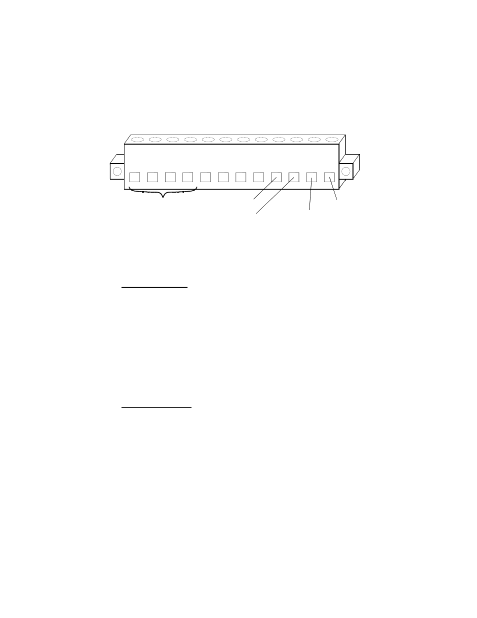
Connection of the DL15-30W wires to the TD77-2
1
2
3
4
5
6
7
8
9
10
11
12
W
H
IT
E
G
R
E
E
N
V
IO
L
E
T
Y
E
L
L
O
W
E
M
P
T
Y
E
M
P
T
Y
E
M
P
T
Y
E
M
P
T
Y
B
L
A
C
K
R
E
D
G
R
O
U
N
D
+
1
2
V
D
C
CONTROL WIRES
BATTERY +
BATTERY -
OUTPUT POWER
TO LIGHTSTICK (+12VDC)
GROUND TO
LIGHTSTICK
1. The TD77-2 control box comes with a removable green terminal block connector on the back
(part #CPSS-153). Remove the terminal block from control box and loosen all 12 terminal
screws. This will open the wire entries.
2. Make the wire connections as shown above, taking care to tighten down each screw once the
appropriate wire is inserted.
Wires From DL15-30W
Yellow: Connect the yellow wire from the lightstick to Terminal 1 of the green
connector. This wire activates the Left Arrow pattern on the arrow stick.
Violet: Connect the violet wire from the lightstick to Terminal 2 of the green
connector. This wire activates the Center Out pattern on the arrow stick.
Green: Connect the green wire from the lightstick to Terminal 3 of the green
connector. This wire activates the Right Arrow pattern on the arrow stick.
White: Connect the white wire from the lightstick to Terminal 4 of the green
connector. This is the Pattern Select wire for the arrow stick. This wire is
optional and may be left unconnected if you do not want the user to change
your pattern options.
Black: Connect the black wire from the lightstick to Terminal 9 of the green
connector. This is the Ground wire to the arrow stick.
Red: Connect the red wire from the lightstick to Terminal 10 of the green connector.
This wire supplies +12VDC to the arrow stick.
Additional Connections
Ground: Using a minimum 18 AWG wire, connect this terminal to the negative of the vehicle
battery (recommended) or a good chassis ground.
+12 VDC: Using a minimum 18 AWG wire, connect this terminal to a +12 VDC source, fused
with a 15A fuse at the source (battery). Star recommends the use of an ignition
switched source to avoid the possibility of draining the vehicle's battery should the
unit be accidentally left on. The lamp brightness will be somewhat diminished if a
large voltage drop exists between the vehicle's battery and the controller. It is
imperative that you supply a ground wire to the terminal marked “GROUND” ("bat -"
on the controller). You must not let the controller's case supply ground.
3. After all of the connections are complete, insert the terminal block into the mating receptacle in
the back of the control box and tighten the two terminal block locking screws on either end of
the block to prevent it from vibrating loose.
(Optional TD77-2 Controller CONT’D)