All heads on and off together (high power only), Set jumper in high/low option position), All heads on and off together (low power only) – Star Headlight & Lantern STAR-PA RSK966P User Manual
Page 7
-4-
(Electrical Connections CONT’D)
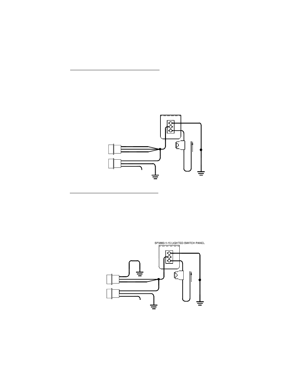
All Heads On and Off Together (High Power Only)
(This setup is typically used for most “On/Off” applications)
For this set up, only one On/Off switch (not included) is necessary.
1. Connect the black wire from the POWER connector to a good chassis ground.
2. Connect all three wires (red, black, and white) from the ENABLE plug and the red wire from
the POWER connector to a +12VDC power source through your On/Off switch.
3. The white wire from the POWER connector will be left unconnected for now. Once your
system is installed, the white wire will be used to program the flash pattern. Proceed to the
Pattern Selection section on page 7.
RP966/RP996
All Heads Activate Together
High Power Only
(Set Jumper in
High/Low Option Position)
WHITE
BLACK
1
SW1
OFF
R
E
D
GOOD
CHASSIS
GROUND
B
L
A
C
K
SP3860-1-15 LIGHTED SWITCH PANEL
(REAR VIEW)
ON
2
3
2
1
3
1
5
A
M
P
F
U
S
E
C
O
N
N
E
C
T
T
O
+
1
2
V
D
C
PLUGS
INTO
POWER
PAK
RED
ENABLE
CONNECTOR
POWER
CONNECTOR
Pattern Select:
Touch and release to +12VDC
to set pattern then tape off
WHITE
BLACK
RED
PLUGS
INTO
POWER
PAK
GOOD
CHASSIS
GROUND
All Heads On and Off Together (Low Power Only)
For this set up, only one On/Off switch (not included) is necessary.
1. Connect the black wire from the POWER connector and the white wire from your
ENABLE plug to a good chassis ground.
2. Connect the red and black wires from the ENABLE plug and the red wire from the POWER
connector to a +12VDC power source through your On/Off switch.
3. The white wire from the POWER connector will be left unconnected for now. Once your
system is installed, the white wire will be used to program the flash pattern. Proceed to the
Pattern Selection section on page 7.
RP966/RP996
All Heads Activate Together
Low Power Only
(Set Jumper in
High/Low Option Position)
RED
PLUGS
INTO
POWER
PAK
ENABLE
CONNECTOR
WHITE
BLACK
PLUGS
INTO
POWER
PAK
POWER
CONNECTOR
WHITE
RED
BLACK
Pattern Select:
Touch and release to +12VDC
to set pattern then tape off
1
SW1
OFF
R
E
D
GOOD
CHASSIS
GROUND
B
L
A
C
K
(REAR VIEW)
ON
2
3
GOOD
CHASSIS
GROUND
2
1
3
GOOD
CHASSIS
GROUND
1
5
A
M
P
F
U
S
E
C
O
N
N
E
C
T
T
O
+
1
2
V
D
C