Wiring, Grounding the module, Input type selection – Spectrum Controls 1762sc-IF8U User Manual
Page 9: System wiring guidelines
MicroLogix™ Universal Analog Input Module
16
Publication 0100151-02 Rev. B
To Select
Make these bit settings
15 14 13 12 11 10 9 8 7 6 5 4 3 2 1 0
500 Pt 385
1 0 0 1 1
1000 Pt 385
1 0 1 0 0
100 Pt 3916
1 0 1 0 1
200 Pt 3916
1 0 1 1 0
500 Pt 3916
1 0 1 1 1
1000 Pt 3916
1 1 0 0 0
10 Cu 426
1 1 0 0 1
100 Ni 618
1 1 0 1 0
120 Ni 672
1 1 0 1 1
604 NiFe 518
1 1 1 0 0
150
ohm
1 1 1 0 1
1000
ohm
1 1 1 1 0
3000
ohm
1 1 1 1 1
Data
Format
Engineering
Units X1
0 0
Engineering
Units X10
0 1
Raw/
Proportional Data
1 0
Scaled for PID
1 1
CJC Temp
Type
(Only when
bit 3 is set)
Raw CJC Temp
x
1
0
Adjusted CJC Temp x
1
1
2/3/4 Wire
RTD
(Only valid for
RTD/R ranges)
2
Wire
0 0
3 Wire w/ Comp
0 1
3 Wire w/o Comp
1 0
4
Wire
1 1
Temperature
Scale
(Only valid for
temperature ranges)
Deg
C
0
Deg
F
1
1
X = don’t care
MicroLogix™ Universal Analog Input Module
9
Publication 0100151-02 Rev. B
Wiring
Grounding the Module
Grounding for this product is provided by the MicroLogix™ 1100 or 1200
CPU via the bus ribbon cable. Refer to Industrial Automation Wiring and
Grounding Guidelines
, Allen-Bradley publication 1770-4.1, for additional
information.
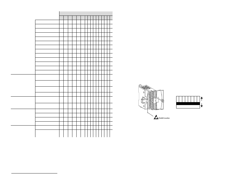
Input Type Selection
Select the input type, current or voltage, using the switch located on the
module’s circuit board and the input type/range selection bits in the
Configuration Data File (see page 15). You can access the switch
through the ventilation slots on the top of the module. The factory default
setting for all switches is Current. Switch positions are shown below.
System Wiring Guidelines
Consider the following when wiring your system:
The analog common (COM) is not connected to earth ground
inside the module. All terminals are electrically isolated from the
system.
Channel to channel isolation is limited to 10 VDC.
1 2 3 4 5 6 7 8
Non‐Current
Current
Channel #