Input data file, Terminal block layout – Spectrum Controls 1762sc-IF8U User Manual
Page 11
MicroLogix™ Universal Analog Input Module
14
Publication 0100151-02 Rev. B
Input Data File
For each module, slot x, words 0 through 7 contain the analog values of
the inputs. The module can be configured to use either raw/proportional
data, engineering units X1, engineering units X10 or scaled-for-PID data.
The input data file for either configuration is shown below.
Configuration, Input and Output Register Format
Register Function
Configuration Registers (NOT USED)
C:e.0 Ignore
C:e.1 Ignore
C:e.2 Ignore
C:e.3 Ignore
C:e.4 Ignore
C:e.5 Ignore
C:e.6 Ignore
C:e.7 Ignore
Input File (Module Data)
I:e.0
Channel 0 Data Word
I:e.1
Channel 1 Data Word
I:e.2
Channel 2 Data Word
I:e.3
Channel 3 Data Word
I:e.4
Channel 4 Data Word
I:e.5
Channel 5 Data Word
I:e.6
Channel 6 Data Word
I:e.7
Channel 7 Data Word
Output File (Used for Module Configuration)
O:e.0
Channel 0 Configuration Word
O:e.1
Channel 1 Configuration Word
O:e.2
Channel 2 Configuration Word
O:e.3
Channel 3 Configuration Word
O:e.4
Channel 4 Configuration Word
O:e.5
Channel 5 Configuration Word
O:e.6
Channel 6 Configuration Word
O:e.7
Channel 7 Configuration Word
MicroLogix™ Universal Analog Input Module
11
Publication 0100151-02 Rev. B
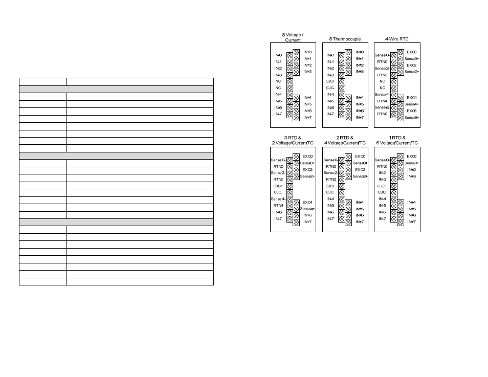
Terminal Block Layout