Minimum spacing, Din rail mounting, Accuracy specifications – Spectrum Controls 1762sc-IF8U User Manual
Page 6
MicroLogix™ Universal Analog Input Module
6
Publication 0100151-02 Rev. B
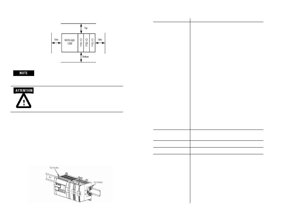
Minimum Spacing
Maintain spacing
from enclosure
walls, wireways,
adjacent
equipment, etc.
Allow 50.8 mm (2
in.) of space on all
sides for adequate
ventilation, as
shown
1762 expansion I/O may be mounted horizontally only.
During panel or DIN rail mounting of all devices, be
sure that all debris (metal chips, wire strands, etc.) is
kept from falling into the module. Debris that falls
into the module could cause damage when power is
applied to the module.
DIN Rail Mounting
The module can be mounted using the following DIN rails: 35 x 7.5 mm
(EN 50 022 - 35 x 7.5) or 35 x 15 mm (EN 50 022 - 35 x 15).
Before mounting the module on a DIN rail, close the DIN rail latch. Press
the DIN rail mounting area of the module against the DIN rail. The latch
will momentarily open and lock into place.
Use DIN rail end anchors (Allen-Bradley part number 1492-EA35 or
1492-EAH35) for environments with vibration or shock concerns.
MicroLogix™ Universal Analog Input Module
19
Publication 0100151-02 Rev. B
Accuracy Specifications
Specification Value
Thermocouple Inputs
Linearization per ITS-90
System accuracy at 25°C (4 and 17 Hz filters):
Type J (-180°C to 1200°C): ± 0.6 degrees C maximum
Type J (-210°C to -180°C): ± 0.8 degrees C maximum
Type N (-160°C to 1300°C): ± 1 degrees C maximum
Type N (-210°C to -160°C): ± 1.8 degrees C maximum
Type T (-190°C to 400°C): ± 1 degrees C maximum
Type T (-270°C to -190°C): ± 7 degrees C maximum
Type K (-200°C to 1370°C): ± 1 degrees C maximum
Type K (-270°C to -200°C): ± 10 degrees C maximum
Type E (-200°C to 1000°C): ± 0.6 degrees C maximum
Type E (-270°C to -200°C): ± 5 degrees C maximum
Type S and R: ± 2.8 degrees C maximum
Type C: ± 1.8 degrees C maximum
Type B: ± 3.3 degrees C maximum
System accuracy at -20-60° C (4 and 17 Hz filters):
Type J (-180°C to 1200°C): ± 1.2 degrees C maximum
Type J (-210°C to -180°C): ± 1.6 degrees C maximum
Type N (-200°C to 1300°C): ± 2 degrees C maximum
Type N (-210°C to -200°C): ± 3.6 degrees C maximum
Type T (-230°C to 400°C): ± 2 degrees C maximum
Type T (-270°C to -230°C): ± 14 degrees C maximum
Type K (-225°C to 1370°C): ± 2 degrees C maximum
Type K (-270°C to -225°C): ± 20 degrees C maximum
Type E (-210°C to 1000°C): ± 1.2 degrees C maximum
Type E (-270°C to -210°C): ± 10 degrees C maximum
Type S and R: ± 6 degrees C maximum
Type C: ± 4 degrees C maximum
Type B: ± 7 degrees C maximum
The above limits do not include the cold junction
compensation or thermocouple sensor errors.
CJC accuracy
± 3.0 degrees C maximum Correlation between
reading and target terminal
CJC Sensor resolution
± 0.2 degrees C max for 0-60C,
± 0.4 degrees C max for full range
CJC Sensor accuracy
± 1.0 degrees C maximum Reading/Conversion of the
sensor
Voltage Inputs
System accuracy at 25° C (4 and 17 Hz filters):
± 20 uV maximum for ± 50 mV inputs
± 20 uV maximum for ± 100 mV inputs
± 3 mV maximum for 0-5V inputs
± 3 mV maximum for 1-5V inputs
± 10 mV maximum for 0-10V inputs
± 10 mV maximum for ±10V inputs
System accuracy at -20-60° C (4 and 17 Hz filters):
± 40 uV maximum for ± 50 mV inputs
± 40 uV maximum for ± 100 mV inputs
± 6 mV maximum for 0-5V inputs
± 6 mV maximum for 1-5V inputs
± 20 mV maximum for 0-10V inputs
± 20 mV maximum for ±10V inputs