Configuration data file – Spectrum Controls 1762sc-IF8U User Manual
Page 10
MicroLogix™ Universal Analog Input Module
10
Publication 0100151-02 Rev. B
Use Belden™ 8761, or equivalent, shielded wire.
Under normal conditions, the drain wire (shield) should be
connected to the metal mounting panel (earth ground) as close
to the module as possible. Keep the shield connection to earth
ground as short as possible.
To ensure optimum accuracy for voltage type inputs, limit overall
cable impedance by keeping all analog cables as short as
possible. Locate the I/O system as close to your voltage type
sensors or actuators as possible.
The 1762sc-IF8U module does not provide loop power for
analog inputs. Use a power supply that matches the input
transmitter specifications.
Digital and analog power must be supplied by an Isolated
Secondary Limited Energy Low Voltage source.
Use supply wires for 20˚ C above surrounding ambient.
For best performance, whenever possible, configure resistance
measurements for 4-wire mode. If using 3-wire mode, ensure
that each lead wire has the same gauge, length and termination.
If using 2-wire mode, the reported measurement will include any
lead wire resistance.
For thermocouple input types, do not remove the CJC sensor
from the terminal block.
MicroLogix™ Universal Analog Input Module
15
Publication 0100151-02 Rev. B
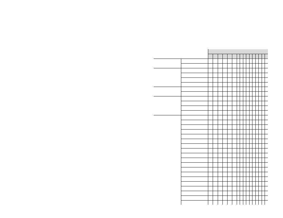
Configuration Data File
The configuration data file is not used. Instead the output data file is
used to configure the module. Take care when making changes to the
configuration (i.e. output data file) while in run mode. Illegal
configurations could fault the controller.
The configuration table is shown below.
To Select
Make these bit settings
15 14 13 12 11 10 9 8 7 6 5 4 3 2 1 0
Channel
Enable
Enable
0
Disable
1
Filter
Frequency
(Ignored if
Display CJC)
17
Hz
0 0
4 Hz
0 1
62
Hz
1 0
470
Hz
1 1
Display CJC
Disabled
0
Enabled
1
Open
Circuit
(Ignored if
Display CJC)
Upscale
0 0
Downscale
0 1
Zero
1 0
Invalid Setting
1 1
Input
Type
(Ignored if
Display CJC)
4 to 20 mA
0 0 0 0 0
0 to 20 mA
0 0 0 0 1
-10 to 10 V
0 0 0 1 0
0 to 10 V
0 0 0 1 1
1 to 5 V
0 0 1 0 0
0 to 5 V
0 0 1 0 1
±100
mV
0 0 1 1 0
±50
mV
0 0 1 1 1
Type
J
TC
0 1 0 0 0
Type
K
TC
0 1 0 0 1
Type
T
TC
0 1 0 1 0
Type
E
TC
0 1 0 1 1
Type
R
TC
0 1 1 0 0
Type
S
TC
0 1 1 0 1
Type
B
TC
0 1 1 1 0
Type
N
TC
0 1 1 1 1
Type
C
TC
1 0 0 0 0
100 Pt 385
1 0 0 0 1
200 Pt 385
1 0 0 1 0