Specifications, System assembly, General specifications – Spectrum Controls 1762sc-IF8U User Manual
Page 8
MicroLogix™ Universal Analog Input Module
8
Publication 0100151-02 Rev. B
Use the table below to determine the maximum number of IF8U modules
that can be installed in a MicroLogix system.
Controller
Max 5V
Bus
Current
Max 24V
Bus
Current
Max # of IF8U
Modules
ML1100 800
700
4
ML1200 (24pt.)
400
350
2
ML1200 (40pt.)
600
500
3
ML1400 (All)
1500
1500
7
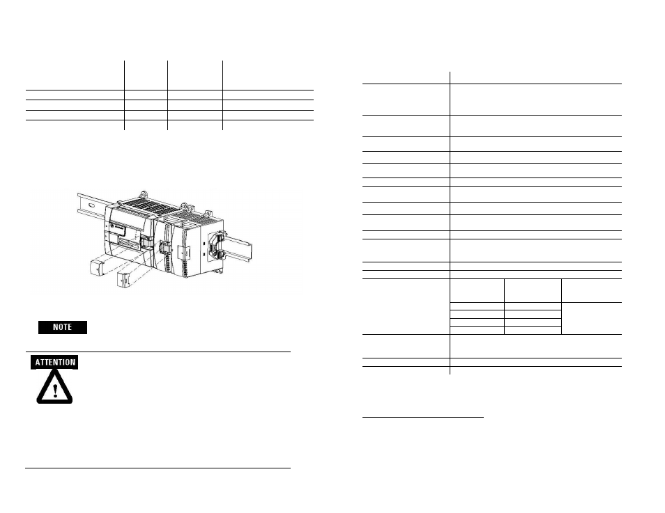
System Assembly
The expansion I/O module is attached to the controller or another I/O
module by means of a ribbon cable after mounting as shown below.
Use the pull loop on the connector to disconnect
modules.
Do not pull on the ribbon cable.
EXPLOSION HAZARD
• In Class I, Division 2 applications, the bus
connector must be fully seated and the bus
connector cover must be snapped in place.
• In Class I, Division 2 applications, all modules must
be mounted in direct contact with each other as
shown on page 6. If DIN rail mounting is used, an
end stop must be installed ahead of the controller
and after the last 1762 I/O module.
MicroLogix™ Universal Analog Input Module
17
Publication 0100151-02 Rev. B
Specifications
General Specifications
Specification
Value
Dimensions
90 mm (height) x 87 mm (depth) x 40 mm (width)
height including mounting tabs is 110 mm
3.54 in. (height) x 3.43 in. (depth) x 1.58 in. (width)
height including mounting tabs is 4.33 in.
Approximate Shipping
Weight (with carton)
268g (0.591 lbs.)
Storage Temperature
-40°C to +85°C (-40°F to +185°F)
Operating Temperature
-20°C to +60°C (-4°F to +140°F)
Operating Humidity
5% to 95% non-condensing
Operating Altitude
2000 meters (6561 feet)
Vibration
Operating: 10 to 500 Hz, 5G, 0.030 in. max. peak-to-
peak
Shock Operating:
30G
Bus Current Draw (max.)
175 mA at 5V dc Max
21 mA at 24V dc Max
Heat Dissipation
1.4W Total Max
Analog Normal Operating
Range
Voltage: -10.5V to +10.5V dc
Current: 0 to +21 mA
Resistance: 0 to 3000 Ω
Resolution
16 bits (Integer Format)
Repeatability
2
±0.1% (With 4Hz or 17Hz ADC Filter)
Channel Update Time
Filter Setting
Conversion Time
Step
Response/Module
Update
3
470 Hz
20 ms
= Conversion
time * (1+ number
of enabled
channels)
62 Hz
45 ms
17 Hz
135 ms
4 Hz
495 ms
Input Group to System
Isolation
Channel to Rack:
707 VDC for 1 minute Optical &
magnetic
Channel to Channel:
10VDC
Module Power LED
On: indicates power is applied and module not faulted.
Recommended Cable
Belden™ 8761 (shielded)
2
Repeatability is the ability of the input module to register the same reading in successive
measurements for the same input signal.
3
The module update time is purely the sum of conversion times for each
enabled channels. The extra addition of 1 is not necessary.