Power requirements, Input specifications, Panel mounting – Spectrum Controls 1762sc-IF8U User Manual
Page 7
MicroLogix™ Universal Analog Input Module
18
Publication 0100151-02 Rev. B
Specification
Value
Vendor I.D.
58
Product Type
10
Product Code
20
Agency Certification
C-UL listed (under CSA C22.2 No. 142)
UL 508 listed
CE compliant for all applicable directives
Hazardous Environment
Class
Class I, Division 2, Hazardous Location, Groups A, B,
C, D
(ISA 12.12.01, C-UL under CSA C22.2 No. 213)
Operating Temperature Code T5
Radiated and
Conducted Emissions
EN55011
Electrical /EMC:
The module has passed testing at the following levels:
ESD Immunity
(IEC61000-4-2)
4 kV contact, 8 kV air, 4 kV indirect
Radiated Immunity
(IEC61000-4-3)
10 V/m, 80 to 1000 MHz, 80% amplitude modulation,
+900 MHz keyed
carrier
Fast Transient Burst
(IEC61000-4-4)
2 kV, 5 kHz
Surge Immunity
(IEC61000-4-5)
1 kV galvanic gun
Conducted Immunity
(IEC61000-4-6)
10V, 0.15 to 80 MHz
4
Input Specifications
Specification
Value
Number of Inputs
8 Current/Voltage or 4 Resistance
A/D Converter Type
Delta Sigma
Common Mode Rejection
100 dB for 4 Hz & 17 Hz Filters
Non-linearity (in percent
full scale)
±0.1%
Input Impedance
Current Terminal: 249Ω
Current Input Protection
±42 mA
Voltage Input Protection
±28 V
5
4
Conducted Immunity frequency range may be 150 kHz to 30 MHz if the Radiated
Immunity frequency range is 30 MHz to 2700 MHz.
5
The maximum allowable voltage difference between any two input pins is
28V.
MicroLogix™ Universal Analog Input Module
7
Publication 0100151-02 Rev. B
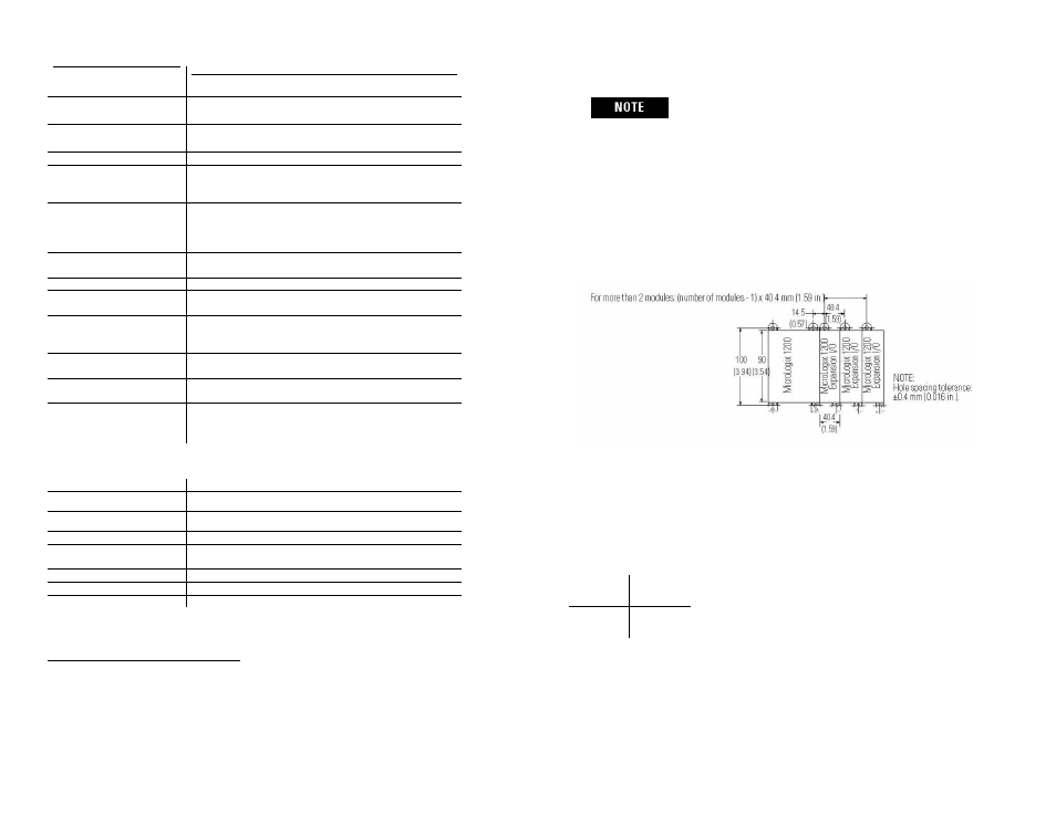
For environments with extreme vibration and
shock concerns, use the panel mounting
method described below, instead of DIN rail
mounting.
Panel Mounting
Use the dimensional template shown below to mount the module. The
preferred mounting method is to use two M4 or #8 panhead screws per
module. M3.5 or #6 panhead screws may also be used, but a washer
may be needed to ensure a good mechanical contact. Mounting screws
are required on every module.
Power Requirements
The maximum number of IF8U modules that can be installed in a system
depends on the maximum bus current draw of the module and the
maximum bus current provided by the PLC. The IF8U module has the
following power requirements.
5 VDC
24 VDC
175 mA 21 mA