Labeling the terminals, Wiring the finger-safe terminal block, Wire size and terminal screw torque – Spectrum Controls 1762sc-IF8U User Manual
Page 12: Addressing
MicroLogix™ Universal Analog Input Module
12
Publication 0100151-02 Rev. B
Grounding the cable shield at the module end only
usually provides sufficient noise immunity. However, for
best cable shield performance, earth ground the shield
at both ends, using a 0.01µF capacitor at one end to
block AC power ground currents, if necessary.
Labeling the Terminals
A write-on label is provided with the module. Remove the label from the
door, mark the identification of each terminal with permanent ink, and
slide the label back into the door.
Wiring the Finger-Safe Terminal Block
Be careful when stripping wires. Wire fragments that
fall into a module could cause damage when power
is applied. Once wiring is complete, ensure the
module is free of all metal fragments.
When wiring the terminal block, keep the finger-safe cover in place.
1. Route the wire under the terminal pressure plate. You can use
the stripped end of the wire or a spade lug. The terminals will
accept a 6.35 mm (0.25 in.) spade lug.
2. Tighten the terminal screw making sure the pressure plate
secures the wire. Recommended torque when tightening
MicroLogix™ Universal Analog Input Module
13
Publication 0100151-02 Rev. B
terminal screws is 0.904 Nm (8 in-lbs).
3. After wiring is complete, remove the debris shield.
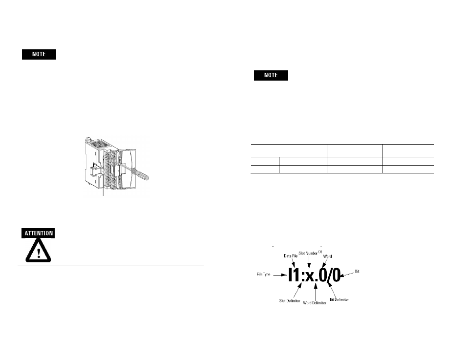
If you need to remove the finger-safe cover, insert a
screw driver into one of the square wiring holes and
gently pry the cover off. If you wire the terminal block
with the finger-safe cover removed, you will not be able
to put it back on the terminal block because the wires
will be in the way
Wire Size and Terminal Screw Torque
Each terminal accepts up to two wires with the following restrictions:
Wire Type
Wire Size
Terminal Screw
Torque
Solid
Cu-90°C (194°F) #14 to #22 AWG
0.904 Nm (8 in-lbs)
Stranded Cu-90°C (194°F) #16 to #22 AWG
0.904 Nm (8 in-lbs)
I/O Memory Mapping
Addressing
The addressing scheme for 1762 Expansion I/O is shown below.
(1)
I/O located on the controller (embedded I/O) is slot 0. I/O added to the controller (expansion I/O) begins
with slot 1.