Installation of restraint – Southbend S Series Restaurant Ranges User Manual
Page 11
OWNER’S MANUAL 1191904 REV 2 (5/14)
PAGE 11
OF 31
S
S
ERIES
R
ESTAURANT
R
ANGES
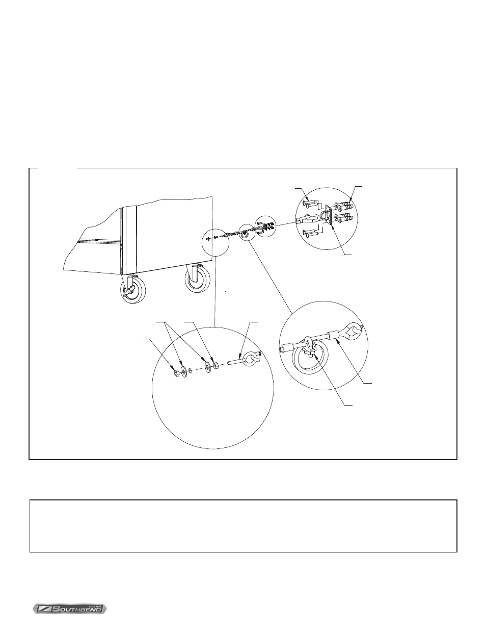
1. Secure the restraining-device bracket (item “B” in the following illustration) to a wall stud located as close as possible
to the appliance connector inlet and outlet connections. Use four #12 screws (items “C”) and plastic anchors (items
“A”) if necessary.
2. Install eye-bolt (item “F”) to a frame member on the rear of the equipment. After checking carefully behind the frame
member for adequate clearance, drill a 1/4” (6 mm) hole through the frame member.
3. Thread hex nut (item “G”) and slide the washer (item “H”) onto the eye-bolt. Insert the eye-bolt through the 1/4”
(6 mm) drilled hole and secure with a washer (item “H”) and nylon lock nut (item “I”).
4. Using the spring-loaded snap hooks, attach the restraining device to the bracket and the eye-bolt.
5. Using the cable clamp (item “D”), adjust the restraining device extended length to prevent over-bending or kinking of
the appliance connector.
Figure 5
Be sure all controls are turned off prior to disconnecting. After reconnecting, be sure all controls are turned off and all
pilots are lit.
NOTICE
Adequate means must be provided to limit the movement of the appliance without depending on the connector and
the quick-disconnect device or its associated piping to limit the appliance movement.
The restraining means should be attached to a frame member on the back of the range.
I
NSTALLATION
F
G
H
I
B
C
E
D
A
Installation of Restraint