Patchmate loop 8 floor top panel, Secondary switch functions - descriptions 1-6 – Rocktron Patchmate Loop 8 Floor User Manual
Page 5
5
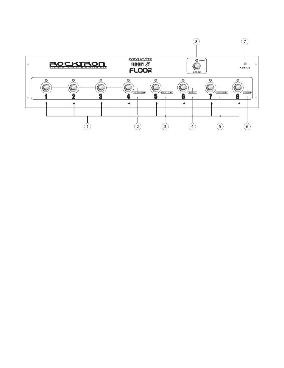
PatchMate LOOP 8 Floor Top Panel
1 LOOP Switches
These switches are used to turn "on/off" each individual loop. The LED above each switch will
display the "current" status of the PatchMate. If an LED above a switch is lit, that LOOP is ac-
tive. If the LED above a switch is not lit, the LOOP is not active or off.
SECONDARY SWITCH FUNCTIONS - DESCRIPTIONS 1-6
These functions are only available once you have entered the "SETUP MODE". To enter the SETUP
MODE, turn the power "ON" - you now have 3 seconds to press the STORE SWITCH once. After the 3
second time out it will enter the SETUP MODE...... and the STORE LED will "blink".
2 CHANNEL/BANK Function
In this function switches 1, 2, 3 and 4 are used to select the MIDI Channel and MIDI Control-
lers Banks. See the section titled "SETUP YOUR PATCHMATE LOOP 8 FLOOR" later in this
manual for the procedure.
3 PRESET DUMP Function
In this function switch 5 is used to dump presets from one PatchMate LOOP 8 Floor to another
PatchMate LOOP 8 Floor. See the section titled "PRESET DUMP" later in this manual for the
proceedure.
4 CANCEL Function
In this function switch 6 is used to CANCEL any secondary function changes that you have
made before you have stored them.
5 STEREO LINK Function
In this function switch 7 is used to select the STEREO LINK function whic allows you to link
LOOPs within the PatchMate Loop 8 Floor for Stereo control. See the section titled "STEREO
LINK" later in this manual for the procedure.