Component summary, Switches and indicators, 4848b reactor controller – Parr Instrument 4848B User Manual
Page 9
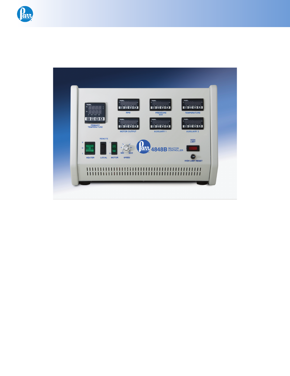
4848B Reactor Controller
w w w . p a r r i n s t . c o m
7
Component Summary
Switches and Indicators
Front Side
4848B Reactor Controller
The Motor Controls consist of an on-off switch
and a speed control knob. The speed control knob
should be turned down to a minimum setting before
turning on the motor switch to minimize electri-
cal surges within the speed control unit. A speed
control know is not included when the reactor is
equipped with an air motor for stirring or when the
controller is created for use with a non-stirred ves-
sel.
If equipped with a motor control module, there will
also be a remote/local switch. When the remote/
local switch is in local mode, the speed control
knob will adjust the motor stirring speed. When the
remote/local switch is in remote mode, the RPM
module will adjust the motor stirring speed. If there
is no motor control module installed, the remote/lo-
cal port will be plugged and the speed control knob
is the sole control for the stirring speed.
The Main Power Switch will cut off power to the
controller. Take care to position the controller such
that the main power switch may be accessed easily
when the controller needs to be disconnected.
The Heater Switch is a manual, three-position, illu-
minated switch which controls the amount of power
sent to the heater. In the HIGH (II) position, full
power is developed by the heater. In the middle (0)
position the heater is off. In the LOW (I) position, a
diode is switched into the system to allow only one-
half of the rated voltage to be supplied to the heater.
This low setting will be most useful when operating
the reactor at temperatures below 175 °C. Power
for the heater is supplied through a solid state relay
controlled by the temperature control module. The
light in the heater switch will glow only when cur-
rent is fl owing to the heater.
The high limit indicator light will glow if the control-
ler receives an indication from any of its sensors
that a high temperature or high pressure limit has
been reached and the High Limit Reset has opened.
When the light comes on, the user must fi nd the
source of the problem, correct it, and then manually
reset the system using the high limit reset button on
the front of the controller.