Instructions for the a2110e motorcontroller, Motor control module (mcm), Motor speed control – Parr Instrument A2110E User Manual
Page 10: Motor controller, Instructions for the a2110e motor controller
Motor Controller
P a r r I n s t r u m e n t C o m p a n y
10
Instructions for the A2110E Motor
Controller
Motor Control Module (MCM)
RPM
This optional module can provide a means for
continuously monitoring the stirring speed in a Parr
reactor. It consists of an optical sensor installed in
the overarm drive on the reactor which is then con-
nected to the A2110E Controller.
The connecting cable has a plug which fi ts the
marked socket on the back panel of the controller.
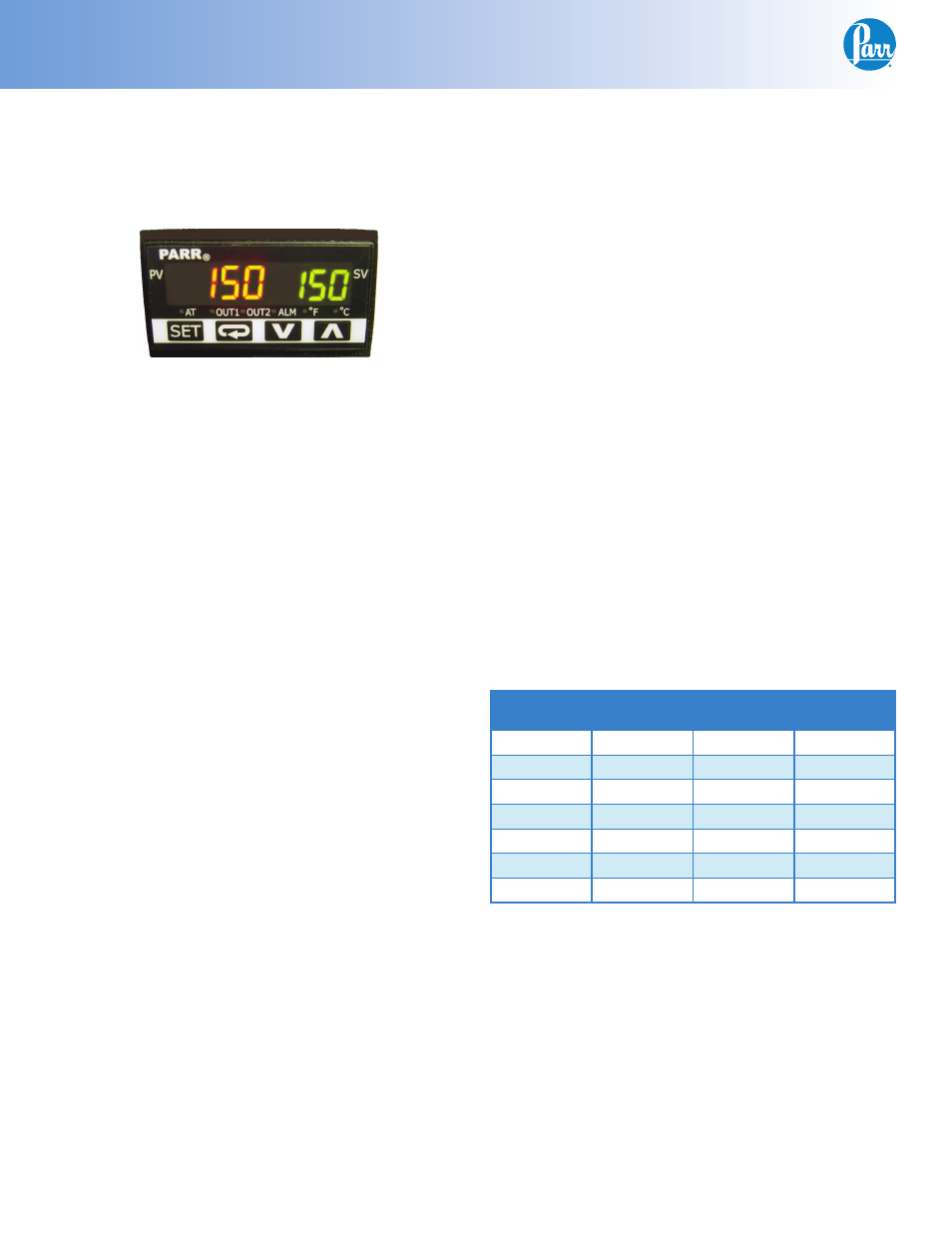
The digital display will show the stirring speed over
a range of 0-2200 rpm with a 1 rpm resolution and
+/- 10 rpm accuracy.
The left display in red shows the stirring speed,
and the right hand display in green shows the rpm
setpoint. The A2110E Controller is designed to run in
either Local or Remote stirring mode. The local/re-
mote switch on the front panel will toggle between
these two modes.
In Local mode, the stirring speed is controlled by
turning the speed control knob on the front panel.
The rpm setpoint has no bearing on the stirring
speed.
In Remote mode, the motor will stir at the rpm set-
point using closed loop PI control. The speed con-
trol knob has no bearing on the stirring speed.
The RPM setpoint may be adjusted by following the
steps below.
Note:
The MCM leaves the factory in STOP mode.
Before the MCM may be used in remote mode it
must be set to RUN mode. Press the circular arrow
key to display the RUN/STOP screen.
For best results, use the RUN/STOP mode as the
fi nal switch. Return the MCM to STOP mode when
the setpoint motor control is not desired, and return
it to RUN mode as the last step to initiate the set-
point motor control.
1. Ensure the local/remote switch is in the REMOTE
position and the motor is motor switch is in the
ON (I) position.
2. Ensure the MCM is in STOP mode. This can be
done by momentarily pressing the return key
(circular arrow) once, then using the up or down
arrow to toggle between run and stop and press-
ing the SET key to solidify the change. Momen-
tarily press the SET key to return to the operat-
ing display.
3. Press the UP arrow key until the red display indi-
cates the desired setpoint. The display will blink
indicating that the value has not been set.
4. Press the SET key to solidify the change and the
display will stop blinking.
5. Return the controller to RUN mode by referenc-
ing step 1 above.
Motor Speed Control
Parr A2110E Controllers are equipped with a solid
state speed control module for use with the variable
speed, DC motors installed on Parr stirred reactors.
The module itself (approximately 4 inches square) is
mounted inside the chassis on the bottom panel. A
motor switch and a speed adjustment potentiometer
are mounted on the front panel. Each speed con-
trol module also requires a resistor matched to the
horsepower of the motor with which it will be used,
as listed in the table below:
Motor
Rating
Motor
Voltage
Resistor
Required
Parr
Number
1/17 HP
90 VDC
0.25 ohm
876E6
1/8 HP
90 VDC
0.10 ohm
876E3
1/4 HP
90 VDC
0.05 ohm
876E
1/4 HP
180 VDC
0.10 ohm
876E3
1/2 HP
90 VDC
0.025 ohm
876E2
1/2 HP
180 VDC
0.05 ohm
876E
3/4 HP
180 VDC
0.035 ohm
876E5
A2110E Controllers furnished as a part of a complete
Parr stirred reactor system will have the proper
resistor installed at the factory. Any controller sold
separately will require a motor specifi cation so that
the proper resistor may be provided.
Always turn the speed control knob fully counter-
clockwise to the off position before turning on the
motor switch, then advance the knob clockwise
slowly to develop the desired speed. Do not over-
load the motor. Any high speed or high viscosity
load which trips the circuit breaker is too heavy.
Reduce the speed to avoid overloading and use the
reset button on the rear panel to restart the motor.