Ntellisys, Alve, Odels – Nor-Cal Intellisys TSS User Manual
Page 13
13
13
Visit our Web Site
www.n-c.com
I
ntellIsys
s
oft
s
hut
TM
G
ate
V
alVe
M
odels
TSS-OP-LiT 08/11
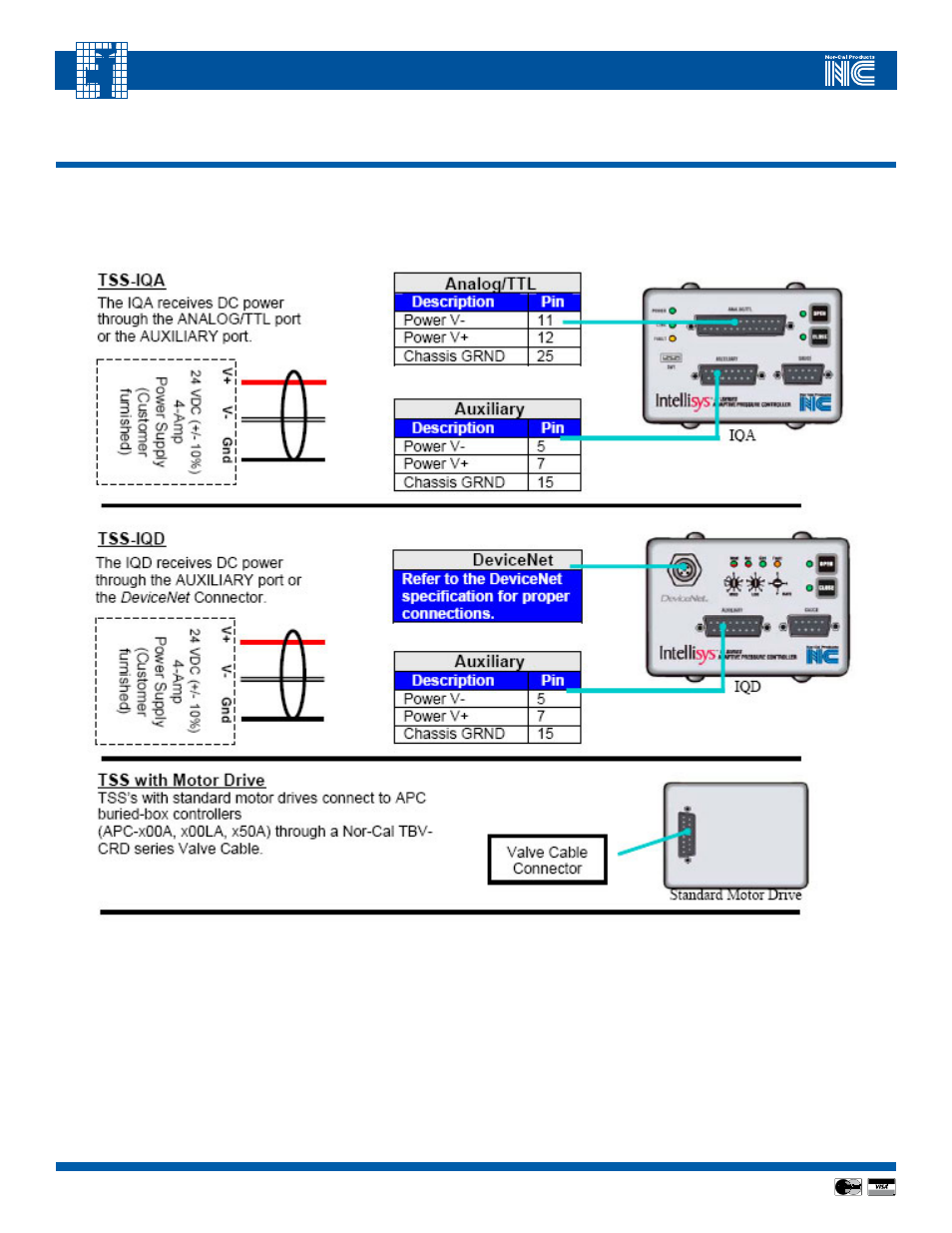
AppENDIx I - Summary Valve and Controller Connection Information
Controller Connection Diagrams
Figures A-1
CAUTION:
Do not connect cables to the valve when the controller is under power.
motor Drive
For valves fitted with a motor-drive unit, connect a Nor-Cal TBV-CRD series valve cable between the motor drive and the buried-box controller.
IqA
For valves fitted with iQA controllers, first confirm that the DiPswitch settings are correct for your serial communications
1
, and then connect the
appropriate cables for Gauges, Auxiliary, and Analog/TTL
2
.
IqD
For valves fitted with iQD controllers, first confirm that the rotary DiPswitch settings are correct for your DeviceNet settings
1
, and then connect
the appropriate cables for Gauges, Auxiliary, Analog/TTL and/or a DeviceNet cable
2
.
1
iQ series DiPswitches are factory-set to default positions. Consult the iQ manual for detailed information on these settings.
2
Refer to the following section for detailed information on cabling requirements and pin-outs for iQ series accessory ports.