Setting the closed positions, Step 28, Step 29 – Mighty Mule FM702 User Manual
Page 29: Step 30, Step 31, Step 32, Step 33, Step 27
25
Step 28
Reattach front mount to gate bracket using a clevis pin, washer, and
hairpin clip. Press the transmitter button to activate the opener and
determine the degree of gate closure. Initially, the push-pull tube
will extend only 7-1/2" until the stroke adjustment knob is set
(see below right). The maximum extension of the push-pull tube is
11
1
/
2
".
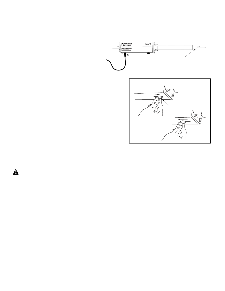
Step 29
To increase the degree of gate closure, loosen the stroke
adjustment knob on the bottom of the opener housing and move it
approximately
1
/
8"
toward the gate bracket (see Fig. A). Finger
tighten the knob (DO NOT USE PLIERS OR OTHER TOOLS
TO TIGHTEN KNOB). Press the transmitter button to check your
adjustment. To decrease the degree of gate closure, move the stroke
adjustment knob away from the gate bracket (see Fig. B).
Step 30
Repeat the procedure in Step 27 until the gate closes firmly as the opener motor shuts down. Each time you adjust the knob,
finger tighten it before pressing the transmitter button to check your adjustment.
If the push-pull tube has been extended too far (i.e., if the knob is too close to the gate bracket), the gate will immediately
reverse and open after closing. When the knob setting is correct, the gate will close firmly, but not sharply, against the
positive stop plate. The motor will run for one-half second after the gate closes against the stop plate. If the motor continues
to run for more than one second, the push-pull tube is overextended and further adjustment is necessary. If the motor strains
too long against the stop plate, the fuse on the control board (above OPERATOR terminal) will be blown. This blade-style
15 ampere fuse (sold by most automotive supply stores) can be easily replaced. NEVER use a fuse rated higher than 15
amperes!
Step 31
Turn the control box power switch OFF. Disconnect the power cable plug from the coupling of the SLAVE operator with
the gate in the fully closed position (do not disconnect the stripped ends on the power cable from the SECOND
OPERATOR terminal block).
Step 32
Repeat Step 25 through Step 28 to connect the 4-1/2 foot power cable and set the closed position for the MASTER gate
leaf. After you have set the closed position for the MASTER gate leaf, bury the PVC conduit and use the appropriate
material to patch the slot in the driveway.
Step 33
Turn the control box OFF and reconnect the power cable plug and the SLAVE operator. Turn the control box ON and retest
the stroke adjustment and sequencing of your dual gate with both openers activated. Make fine adjustments to the stroke
knob position and set the SEQ1 and SEQ2 DIP switches if necessary. NOTE: Only make changes to the DIP Switches when
the Control Box is turned OFF.
Stroke Adjustment Knob
Figure A
Moving knob toward
the gate bracket
increases gate closure.
Figure B
Moving knob away
from the gate bracket
decreases
gate
closure.
Step 27
Carefully insert the power cable plug (of the
SLAVE power cable) into the coupling at the rear of
the opener. Turn the plug until it aligns with the
pins in the coupling. Push the plug into the
coupling until it stops. Finger tighten the sleeve nut
to lock the plug into position.
®
E-Z GATE OPENER
Push-Pull Tube
Attach Power Cable Plug
Setting the Closed Positions
HINT: The easiest way to make sure your dual gate closes fully is to set the closed position for each gate leaf one at a time.
Set the closed position for the SLAVE gate.