Installation of the positive stops, Step 14, Step 13 – Mighty Mule FM702 User Manual
Page 21: Step 15, Important
17
Step 14
Attach a vertical closed position stop plate to the SLAVE or SECOND gate.
Remove hairpin clip, clevis pin, and washer from front mount and close the gate leaf (remember to support opener). The stop
plate needs to be positioned near the end of the gate as shown in Illustration A. Position this closed position stop plate
vertically and fasten it to the inside bottom (i.e., SLAVE opener side) of the gate frame, but do not tighten it completely.
NOTE: For a push-to-open installation (gate opens out from the property) attach the closed position stop plate to the outside
of the gate.
Step 13
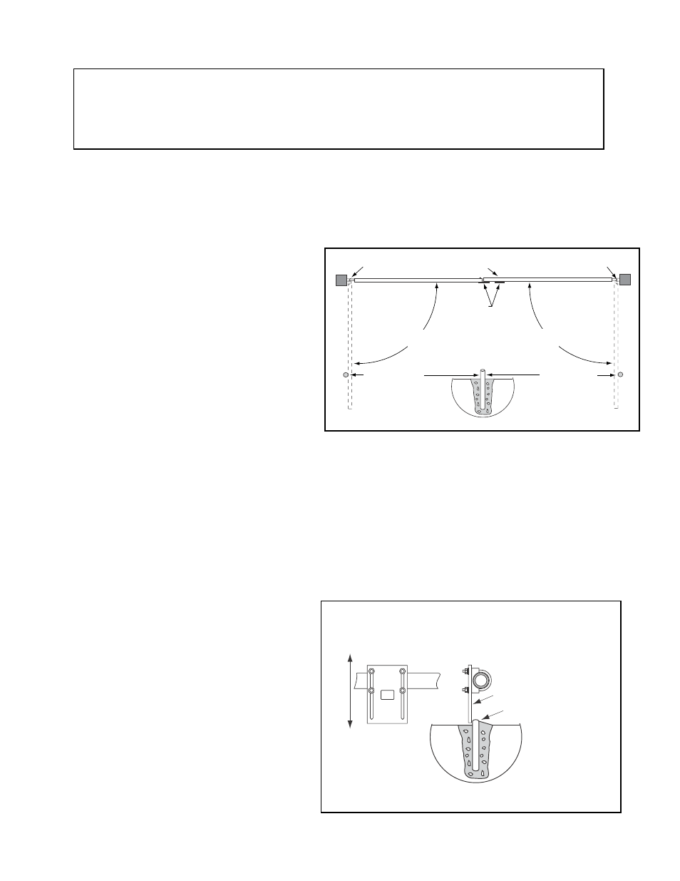
Open position stops are required for both gate leaves
(see illustration at right).
With the gate leaf at its maximum open position, measure
the distance from the gate hinge to the end of the leaf.
At approximately
2
/
3
of this distance (using the hinge as
your starting point), place a mark on the ground directly
under the gate leaf. Install the open position stop at this
mark (see illustration). The open position stop post may
be made of wood, metal, or concrete and should be
firmly secured in the ground (we recommend setting it in
concrete). When the open position stop post is in the
ideal position, the gate leaf will strike the post just as the
opener motor shuts down. Repeat this step for the
other gate leaf.
Step 15
Install a low profile ground stop (not provided)
beneath the SLAVE gate stop plate.
The low profile ground stop may be made of metal or
concrete and should be firmly secured in the ground
(we recommend setting it in concrete). You must
slide the closed position stop plate toward the ground
stop until they touch (see Illustration B at right and
the overview illustration on page 18). Once you
have moved the stop plate to the correct position,
tighten its hardware completely.
Closed Position
Stop Plates
Open Position Stop
Wood, metal, or concrete
post set in concrete.
Gate Hinge
Gate Hinge
Open Position Stop
The gate leaf must open
80˚ (min.) to 110˚ (max.)
Ground Stop
(beneath gate)
The gate leaf must open
80˚ (min.) to 110˚ (max.)
MASTER GATE
SLAVE GATE
Closed Position Stop Plate mounted
on the gate leaf that CLOSES FIRST
Closed Position Stop Plate
Low Profile Ground Stop
in Near the Center of Driveway
FRONT VIEW
SIDE VIEW
Mount Vertically
Installation of the Positive Stops
The Mighty Mule Gate Opener
®
firmly holds the gate in the open and closed positions against the positive stops.
The positive stops form the boundaries of the gate operating arc and help stabilize the gate leaves. Furthermore,
stable gate leaves help to maintain the long life of your automatic gate opener system. To further enhance stability
and security, we strongly recommended using an optional Mighty Mule Automatic Gate Lock
®
(see Accessory
Catalog) with your dual gate.
IMPORTANT:
You need to determine which side of the driveway you will mount the control box. From this point on
the gate and gate opener on the same side as the control box will be refered to as the MASTER or FIRST gate and gate
opener. The gate and gate opener on the opposite side of the driveway from the control box will be refered to as the SLAVE
or SECOND gate and gate opener.
llustration A
Illustration B