Mounting the control box, Step 20, Step 17 – Mighty Mule FM702 User Manual
Page 23: Step 18, Step 19
19
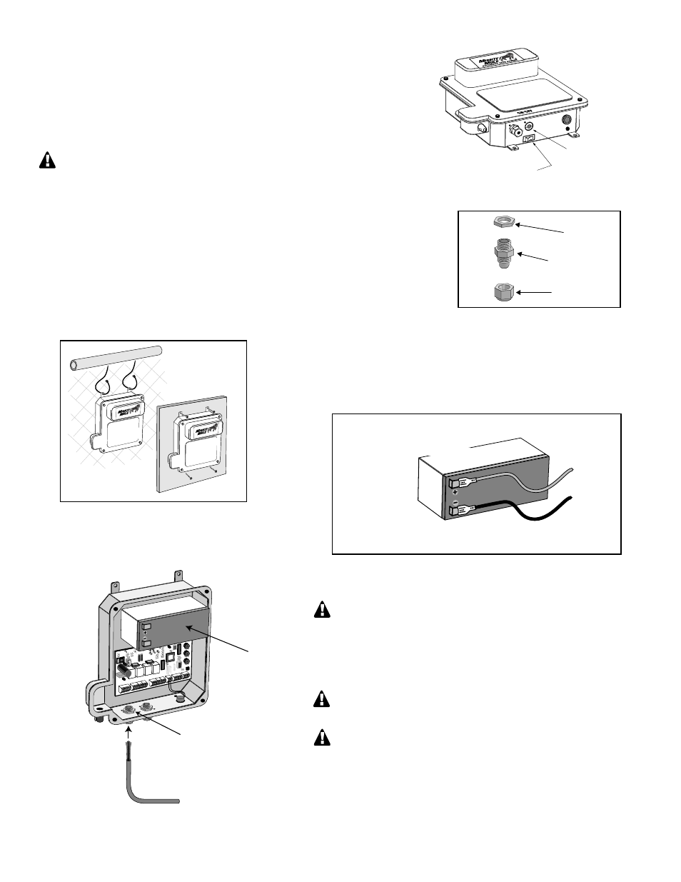
Step 20
Make sure the control box power switch is in the OFF
position. Slide the battery into position with its terminals to
the left (see illustration). Push battery down until it fits snugly
in control box. Connect the BLACK battery wire to the
NEGATIVE (–) battery terminal. Connect the RED battery
wire to the POSITIVE (+) terminal.
Pay close attention to the color of the wires. If the wires are
connected incorrectly, the control board will be damaged.
NEVER insert the battery with the terminals to the right!
HINT: A dab of household petroleum jelly on the battery
terminals will help prevent corrosion.
Mounting the Control Box
Sealing Nut
Hub
Lock Nut
Strain Relief
Step 17
Remove the four thumb screws from the control box cover and remove the cover.
Use a screwdriver or steel punch to carefully remove the thin plastic knockout disk
(see illustration at right) from the second opener power cable hole at the bottom of
the control box.
Be careful to avoid contact or damage to the control board with tools.
Use a sharp knife or deburring tool to clean the rough edges from the hole.
AUTOMATIC GATE OPENER
®
AUTOMATIC GATE OPENER
®
Step 18
The strain relief for the first opener power cable comes from the factory installed.
The second power cable strain relief will be installed the same way. Unscrew and
remove the lock nut from the strain relief (included with hardware). From the
outside of the control box, insert the strain relief hub and sealing nut (see
illustration right) into the new strain relief hole. Finger tighten the lock nut onto
the threaded end of the strain relief hub from inside the box.
Step 19
Mount the control box using the nylon cable ties (provided) or
another secure method. The control box must be mounted at least
3 feet above the ground to protect it from rain splash, snow, etc.,
and at least 3 feet from an ac power source to prevent electrical
interference.
Knockout Disk
OFF
Opener Power Cable
R
E
D
B
L
K
O
R
G
B
L
U
G
R
N
C
L
S
E
D
G
O
P
N
E
D
G
R
E
D
G
R
N
O
R
G
B
L
U
W
H
T
B
L
K
O
R
G
B
L
U
G
R
N
C
L
S
E
D
G
O
P
N
E
D
G
LEARN
AUTO
CLOSE
INERTIA
STATUS
STATUS
BATT
BATT
+
–
OBSTR.
SENS.
RCVR
R G
B
ALARM
SECO
ND O
PERATO
R
FIRST O
PERATO
R
POW
ER IN
18VAC SO
LAR
~ ~ – +
ACCESSO
RY
PWR. SW.
PWR. SW.
Left Strain Relief
12 V Battery
RED wire to POSITIVE (+) terminal
BLACK wire to NEGATIVE (–) terminal
RED
BLACK