Powering the system, Connecting the battery, Installation of the gto transformer – Mighty Mule MM-SL2000B User Manual
Page 20: Step 1, Step 8, Step 3, Step 2, Step 4
8
SL-2000B Instruction Manual 04.26.12
POWERING THE SYSTEM
Step 1
Make sure the control box power switch is in the
OFF position.
ON-OFF
OFF
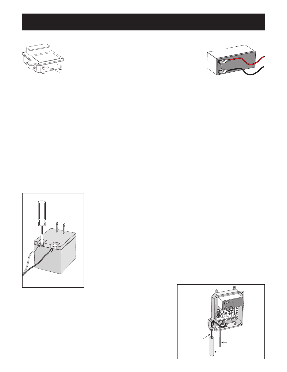
Step 8
Unscrew and remove the front cover of the control box
and slide battery into position with its terminals to the
left (see illustration). Make sure the battery fits snugly in control box.
Connect the black battery lead to the negative (–) terminal, and the red battery lead to the positive (+)
terminal. DO NOT allow battery leads to touch the control board! Touching the control board with battery
leads can short circuit the system!
RED
WIRE
to positive (+)
BLACK
WIRE
to negative (–)
Connecting the Battery
Choose the electrical outlet into which the transformer will be plugged. Measure the distance from the
electrical outlet to the control box, following the path where the low voltage wire will run (the maximum
distance can be no more than 1000 ft.).
Installation of the GTO Transformer
Step 3
Strip
3
/
16
” off the ends of the low voltage wire and attach ends to the
transformer terminals.
To prevent damage to transformer, make sure the exposed wire ends
do not touch each other!
NOTE: Wires coming from the ground to the control box should be run
through PVC conduit to protect them from damage.
Feed the low voltage wires upward through the strain relief on the bottom
of the control box (see Illustration J).
Illustration I
Step 2
Run the low voltage wire from the electrical outlet to the control box. Do not exceed 1000 ft..
NOTE: Pull approximately 1 ft. of low voltage wire into the control box to accommodate terminal
connections. To maintain adequate charging power, use appropriate gauge, stranded, direct burial wire
(see Accessory Catalog).
RED
BLK
ORG
BL
U
GRN
CLS EDG
OPN EDG
RED
GRN
ORG
BL
U
WHT
BLK
ORG
BL
U
GRN
CLS EDG
OPN EDG
LEARN
AUTO
CLOSE
INERTIA
BATT
+
–
OBSTRUCT
SENS.
RCVR
R G B
ALARM
SECOND OPERA
TOR
FIRST OPERA
TOR
POWER IN
18VAC SOLA
R
~ ~
– +
ACCES
SORY
PWR. SW
.
Operator Power Cable
PVC Conduit
Low Voltage Wire
from AC Transformer
Illustration J
Step 4
Strip
3
/
16
” off the ends of the low voltage wire and twist tightly.
These wire ends will be attached to the control board at the
18VAC terminals located on the POWER IN terminal block (see
Illustration L). Wire sheathing should not come in contact with
terminals, however, it should not be stripped so far that wires can
come in contact with one another (see Illustration K).