Lodar 4 Function AC relay Receiver, Master and IP Series Transmitter User Manual
Page 3
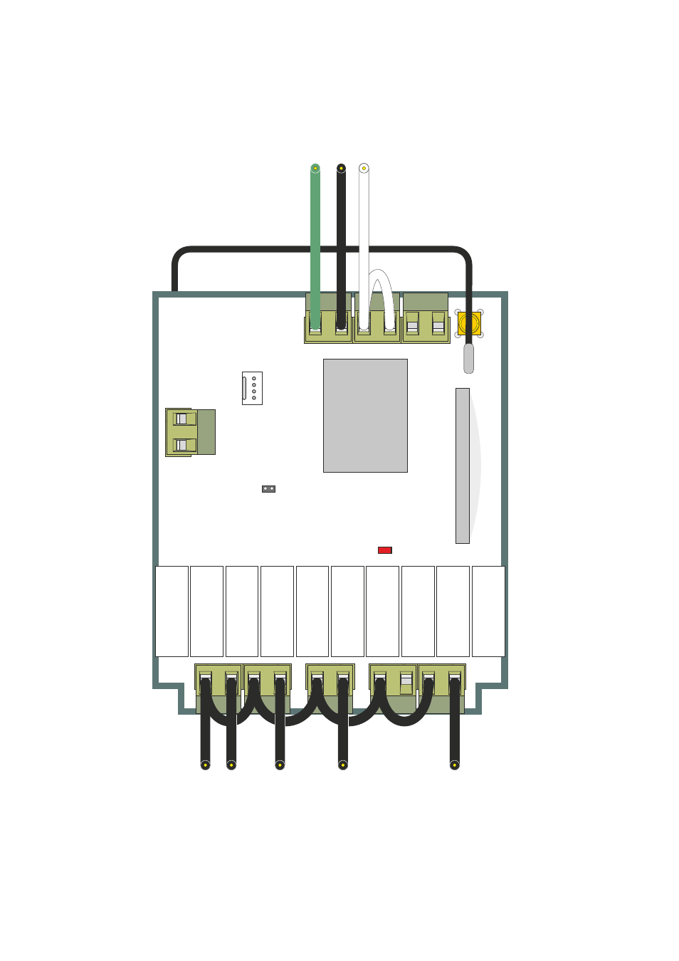
F1
Safety
F1
Switch
F2
Safety
F2
Switch
F3
Safety
F3
Switch
F4
Safety
F4
Switch
M
Safety
M
Switch
Power Supply
90 - 264 V
AC
for control circuits
ST -
LK1
LK2
RS232
ANT
Radio Module
Internal Aerial
glue
Connection Detail - Switch V
oltage and Supply V
oltage are the same
Earth
Live
Neutral
Loop wire
connecting
N
to N
C
S
Important
The Receiver
will not work
without this
connection
*If a switch is not used, its input must still be wired, otherwise if its corresponding
T
ransmitter Function is operated in error the Receiver will immediately switch of
f.
Common Live
Output 1
Output 2
Output 3
Master Output
Common Live Loop
Important
ALL
inputs must
be wired
*
see note below
W
ire is not supplied with Lodar 96 and 97 Series systems, local wiring regulations apply
This manual is related to the following products:
- 2 Function AC relay Receiver, Master and IP Series Transmitter 2 Function AC relay Receiver and IP Series Transmitter 4 Function AC relay Receiver, Master and Standard Transmitter 2 Function AC relay Receiver, Master and Standard Transmitter 2 Function AC relay Receiver and Standard Transmitter 2 Function AC relay Receiver and Mini Transmitter