Receiver detail – Lodar 4 Function AC relay Receiver, Master and IP Series Transmitter User Manual
Page 2
in
F
1
o
u
t
in
F
2
o
u
t
in
F
3
o
u
t
in
F
4
o
u
t
in
M
o
u
t
F1
Safety
F1
Switch
F2
Safety
F2
Switch
F3
Safety
F3
Switch
F4
Safety
F4
Switch
M
Safety
M
Switch
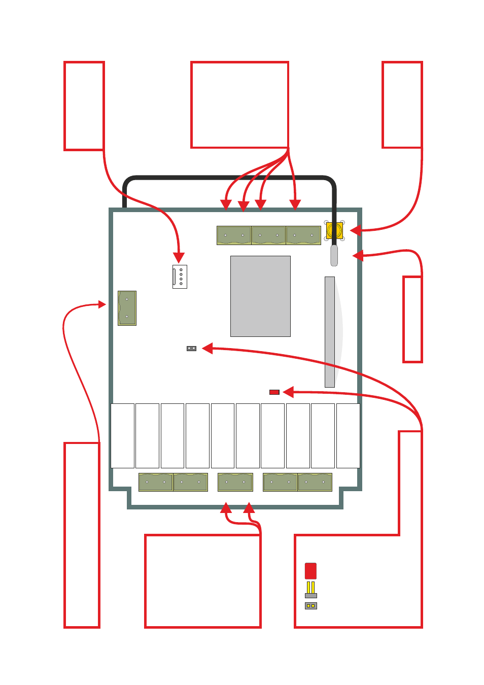
Power Supply
90 - 264 V
AC
for control circuits
ST -
E
L
N
C
N
S
N
S
N
S
LK1
LK2
RS232
ANT
Radio Module
Internal Aerial
glue
SMA
connector for
External
Aerial
Antenna
Part No. 9861, 9862,
9863 or 9869
Supply 90 to 264 V
AC
E = Earth
L
= Live
N
= Neutral
(control circuit)
C
N
= Neutral
(switch circuit)
S
Standard (Internal)
Antenna
connection
Receiver Detail
ST
OP
and - (5 V
olt circuit), when connected together
will cause the Receiver to power down.
RS232 connection
for programming and
special features
LK1
, when bridged
causes the Master
Output to be
Parallel
LK2
, when bridged
causes the Master
Output to be
Continuous
POWER DOWN RECEIVER BEFORE MAKING CHANGES
Outputs sockets
F1& F2, F3, F4, & Master
.
in = common live
out
= load
Each output is designed
to handle 10
Amps Max,
current draw in excess
of this will damage the
Receiver
.
- 2 Function AC relay Receiver, Master and IP Series Transmitter 2 Function AC relay Receiver and IP Series Transmitter 4 Function AC relay Receiver, Master and Standard Transmitter 2 Function AC relay Receiver, Master and Standard Transmitter 2 Function AC relay Receiver and Standard Transmitter 2 Function AC relay Receiver and Mini Transmitter