Manual transmission with linelock & nitrous – Lingenfelter L460095297 Lingenfelter LNC-002 Launch Controller v2.0 User Manual
Page 12
Page 11 of 17
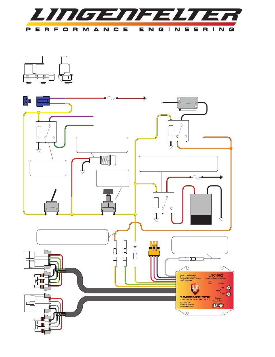
Manual Transmission with Linelock & Nitrous
A
B
C
1
1 - Locate CPP (Clutch Position Switch) and unplug 2-wire connector.
2 - Cut wires appox. 3" back from connector.
3 - Find +12 volt Key On power source and connect to one wire of CPP connector.
4 - Splice two wires onto remaining CPP connector wire and connect one wire to #85 on Relay.
The extra wire will be used for LNC-002 Launch Controller activation.
5 - Connect terminal #86 on Relay to Ground.
6 - Connect wires cut from CPP Switch connector to Terminals #30 and #87 as shown.
Wire color illustrated is
for 1999 TransAm
+12V
Fuse
5 Amp
85
86
30
87a
87
2
3
6
4
Ground
5
Connect wires cut from CPP
Switch connector in Step 2
to Relay as shown.
General purpose
Automotive Relay.
5 to 40 Amp
Toggle Switch
Arms Linelock
and 2-Step
Ground
Momentary
Switch
85
86
30
87a
87
Ground
Linelock
Solenoid
+12V
Ground
Optional LED, On when
Arming Switch is ON and
Clutch Pedal is depressed.
Remove Switch and
wire direct to make
2-Step active with
clutch switch only.
Relay can be omitted if Linelock Solenoid
has a lower current/amp draw than the
Momentary Switch rating.
Analog Output
0-3 volt, .2 volt per 1* of Retard
Connect to analog input of Data
Recorder.
Retard Activation Connect to Nitrous
WOT switch signal or to +12V output
from Nitrous controller.
WOT Switch
85
86
30
87a
87
Ground
To Nitrous Relay
When the LNC-002 is powered up with no
MAP Sensor installed it will default to
Time Based Retard mode.