Programming analog input signal range – Lingenfelter L460160000 Lingenfelter RPM-003 RPM Activated Switch Instructions v1.5 User Manual
Page 6
Page 5 of 17
Additional Notes and Warnings:
• Changes to the switch settings must be done with the RPM-003 powered off.
• The switch positions are only read on start up.
• The low RPM setting (RPM #1) must be less than the high RPM setting (RPM #2) if both are non-zero values (window
switch mode). If RPM #1 is greater than or equal to RPM #2, the outputs can never be active because the condition can
never be met.
• The RPM Controlled Switch will not work at RPM levels below 400 RPM.
• The minimum difference between the ON RPM and the OFF RPM when in Window Switch mode is 500 RPM.
• The minimum difference between the minimum and maximum analog voltage is 1.5 volts.
• Make sure that the RPM-003 ground wire is sufficiently secured to a vehicle ground. Failure to fully secure the RPM-003
ground wire to a vehicle ground source could cause the RPM-003 to malfunction
• Do NOT submerge the module in liquid or directly wash the unit with liquid of any type! The switches on the RPM-003 are
sealed but are NOT rated for high pressure washing, use caution if power washing near the RPM-003 module.
•
Do NOT mount the RPM-003 directly on top of the engine or near the exhaust manifolds due to heat concerns.
•
Do NOT mount the RPM-003 in the line of site of high temperature objects such as exhaust manifolds, turbine housings
etc. If needed, install a heat shield in between the heat source and the module to protect the plastic case.
•
Do NOT install within 6” of nitrous solenoids or other devices with strong magnetic fields.
•
Do NOT install near the spark plugs or the spark plug wires (or other potential strong sources of electrical noise).
•
LPE recommends the use of resistor type spark plugs and RFI (radio frequency interference) and EMI (electromagnetic
Interference) suppression spark plug wires on all EFI engines and any vehicle that has electronic control modules on board
(including the RPM-003). Failure to do so may result in erratic operation of electronic devices including the RPM-003.
• It is important to note that the throttle on an electronic throttle body is usually not fully closed with the vehicle keyed on
and the engine off. Because of this, the analog input trip point of 90% on the RPM-003 may not match the 90% TPS value
displayed on the scan tool.
• The connection of this device to an electronic throttle body should be done on off-road and racing applications only.
• Caution must be taken if you are going to wire the purple analog input wire from the RPM-003 into the wire
that relays the throttle position between the ECM and an Electronic Throttle Body. On Electronic Throttle Body
equipped (or drive-by-wire) vehicles, DTC codes or even a disabled vehicle could result if the electronic throttle
body loses its connection to the ECM. While every effort has been made by LPE to test the RPM-003 on a variety
of vehicles, we can not guarantee that this module will work with every electronic throttle currently in use. If this
module causes the ECM to set a code or causes any other engine operation issues, disconnect and discontinue the use
of this module IMMEDIATELY.
Programming Analog Input Signal Range:
1. To put the RPM-003 in programming mode, all four 10 position switches
must be set to zero and the 16 position switch must be set to 0.5, low range
(arrow pointing straight up). The position of the DIP Switches do not have
to be changed. Upon powering up the unit, the LED on the RPM-003
should now be blinking GREEN.
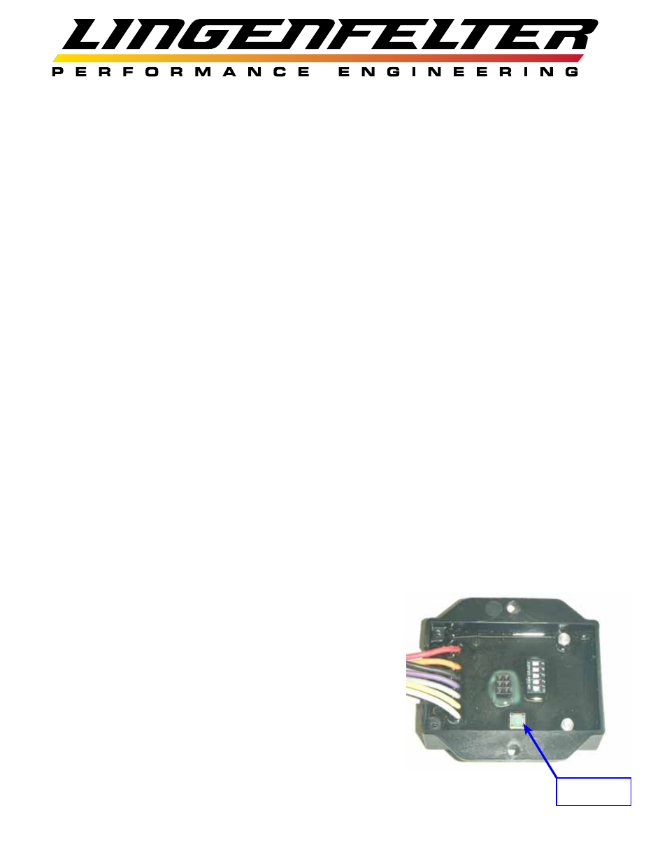
2. Using a #1 Phillips head screwdriver, remove the back cover on the
RPM-003 to access the green programming button. The location of the
programming button is shown in the adjacent illustration.
Programming
Button