Rpm-003, Table a - wiring (also labeled on module), Settings – Lingenfelter L460160000 Lingenfelter RPM-003 RPM Activated Switch Instructions v1.5 User Manual
Page 3
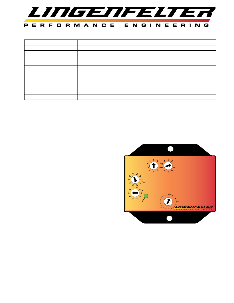
Table A - Wiring (also labeled on module):
Wire color
Label
Notes
Red
+12 Vdc
Connects to a switched and fused +12 volt DC source.
Orange
Normally Off +12
Vdc Output
This is the normally open (off) +12 Vdc output wire. +12 Vdc will flow through this wire when
the switch is activated. This connects to the +12 Vdc side of the device you plan to control.
Black
Ground
Connects to a vehicle ground.
Purple
Analog Input
This connects to the analog signal output wire of a clutch pedal position sensor, throttle position
sensor, MAP sensor, or other rising or falling 0-5 volts signal sensors.
Gray
Normally On
Ground Output
This is the normally closed (on) ground output wire. This wire will open the ground path when
the switch is activated. This connects to the ground side of the device you plan to control.
Yellow
Normally Off
Ground Output
This is the normally open (off) ground output wire. This wire connects to ground when switch is
activated. This connects to the ground side of the device you plan to activate.
White
Tach Input
This is the RPM input wire. This connects to your RPM signal wire.
Settings:
• Controlled by one sixteen position switch, four ten position switches, five DIP switches, and one push button.
Settings on the front face of the RPM-003:
• Single sixteen position switch for selecting pulse per revolution count. Refer to Table B on page 15 for a list of various
vehicle applications and their correct pulse per revolution setting.
• First half of the range is the Low Range (9,900 &
below). Low range should be selected if the RPM
switch point will occur below 9,900 RPM.
• Second half of the range is for the High Range
(10,000+ RPM). High Range mode should be used if
the RPM switch point will occur above 9,900 RPM.
High Range mode only applies to the RPM #2 range.
• Two ten position switches for selecting the RPM #1
• RPM x1000
• RPM x100
• If set to zero, the RPM-003 functions in RPM switch
mode. With RPM #1 set to zero, the outputs will be
swapped from what is labeled on the RPM-003 (i.e.
+12 normally OFF output is now normally ON) until
RPM #2 is reached. See the activation charts on page
16 for clarification of the switch logic.
• If RPM #1 and RPM #2 are both non-zero, the RPM-
003 functions as a window switch, which means that
the outputs will change their condition when the first
switch point is reached, and then will switch back to the their original condition when the second switch point is
reached. See the activation charts on page 16 for clarification of the switch logic.
• Two ten position switches for selecting the RPM #2
• RPM x1000 (10000 RPM is added to this setting when in High Range)
• RPM x100
• If set to zero, the RPM-003 functions in RPM switch mode. With RPM #2 set to zero, the outputs will remain
as labeled on the RPM-003 until RPM #1 is reached. See the activation charts on page 16 for clarification of the
switch logic.
• RPM #1 MUST BE LESS THEN RPM #2 IF BOTH SETTINGS ARE NON-ZERO VALUES.
Page 2 of 17
Power
RPM-003
RPM Window Switch
Ground - Black
Normally On - Gray
Normally Off - Yellow
with Analog Input
RPM #1 x1000
RPM #1 x 100
+12V Switched Power - Red
RPM #1
RPM #2 x1000
RPM #2 x100
RPM #2
Analog Input Signal - Purple
+12V Output Norm Off - Orange
Tach Input Signal - White
.5
1
2
3
4
5
1.5
2.5
.5 1
1.5
2
2.5
3
4
5
High Range
+10,000 Off Rpm
Low Range