Activation reference charts – Lingenfelter L460160000 Lingenfelter RPM-003 RPM Activated Switch Instructions v1.5 User Manual
Page 17
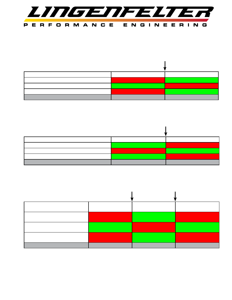
Activation Reference Charts
Example 1:
• RPM Switch mode
• RPM 1 = 2500 RPM
• RPM 2 = 0 RPM
Output (Wire Color)
Output state below RPM 1
Output state above RPM 1
+12v activation normally OFF (Orange)
OFF
ON
Ground activation normally ON (Gray)
ON
OFF
Ground activation normally OFF (Yellow)
OFF
ON
RPM-003 LED status
solid GREEN
blinking GREEN
Example 2:
• RPM Switch mode
• RPM 1 = 0 RPM
• RPM 2 = 2500 RPM
Output (Wire Color)
Output state below RPM 2
Output state above RPM 2
+12v activation normally OFF (Orange)
ON
OFF
Ground activation normally ON (Gray)
OFF
ON
Ground activation normally OFF (Yellow)
ON
OFF
RPM-003 LED status
blinking GREEN
solid GREEN
Example 3:
• RPM Window Switch mode
• RPM 1 = 2500 RPM
• RPM 2 = 6500 RPM
Output
(Wire Color)
Output state
below RPM 1
Output state between
RPM 1 and RPM 2
Output state
above RPM 2
+12v activation normally OFF
(Orange)
OFF
ON
OFF
Ground activation normally ON
(Gray)
ON
OFF
ON
Ground activation normally OFF
(Yellow)
OFF
ON
OFF
RPM-003 LED status
solid GREEN
blinking GREEN
solid GREEN
NOTE: If the analog input is enabled on the RPM-003, both the RPM and the analog voltage criteria must be met for the RPM-
003 to switch the outputs as shown above. For the analog voltage criteria to be met, the clutch or throttle must reach at least
90% of it’s travel (clutch pedal at least 90% depressed, throttle body at least 90% open).
Engine
RPM = 2500
Engine
RPM = 6500
Engine
RPM = 2500
Page 16 of 17
Engine
RPM = 2500