Opening the torso, Attaching the left leg, Maintenance – Laerdal SimMan Essential Bleeding User Manual
Page 33: Attaching or replacing limbs, Maintenance tasks, Left leg to pelvis – cable and tube descriptions
33
MAINTENANCE
Opening the Torso
Open the Patient Simulator torso for the following procedures:
Attaching or Replacing Limbs
− Attaching or dismantling the Patient Simulator legs and arms.
− Exchanging default arms for optional IV or trauma arms.
Maintenance Tasks
− Changing the Patient Simulator batteries.
− Replacing the Pneumothorax Bladders, Chest-Rise Bladders,
Lung Bladders, IO Modules and Chest Drain Modules.
− Replacing the Torso Skin.
− Performing a general inspection.
− Removing WLAN adapter.
To open the Torso Skin
1 Unzip the zippers on the Patient Simulator’s left shoulder and
torso.
2 Remove the genitalia module and release the skin flap from the
pelvis.
3 Fold the Torso Skin over to one side.
4 Open the Stomach Foam to one side, taking care not to tug on
the connecting tubes and cables.
Note: DO NOT disconnect the tubes and cables connecting the
Stomach Foam to the Patient Simulator.
5 Replace the Stomach Foam and close the Torso Skin, perform
steps 1- 4 in reverse.
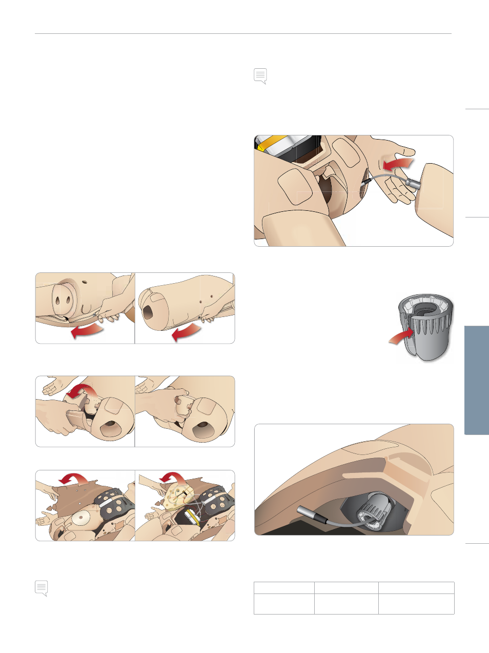
Attaching the Left Leg
Note: Assemble the Patient Simulator on a large flat surface. Attach
the Left Leg before the Right Leg..
Open the torso to access the hip joint connectors. To open the
torso follow steps 1 – 4, Opening the Torso.
1 Align the left leg bolt and cable with the pelvis socket.
2 Feed the leg bolt and cable through the socket and into the
torso. Do not pull the leg by the cable.
3 Carefully push the leg in towards the pelvis to form a snug fit.
Hip joint connector with side slot for
inserting cable (shown right)
4 Position the connector rounded end
facing downward. Place the leg cable
into the side slot of the connector.
5 Slide the connector downwards along
the cable and onto the leg bolt. Ensure
that the nut and bolt are aligned, and that all cable are secured
within the connector.
6 Screw the connector onto the leg bolt. Avoid twisting the cable.
Tighten the connector so that the leg is able to rotate freely
around the hip joint connector.
7 Connect the corresponding leg cable as shown in the following
table:
Left Leg to Pelvis – Cable and Tube Descriptions
Name/Label
Tube/Cable Color
Connector Description
Left Pedal
Grey cable
black with silver
coloured connector
Cautions
and
W
arnings
Featur
es
Setup
Maintenance
Spar
e Par
ts
Tr
oubleshooting