Advanced system, Introduction to simjunior advanced, Setup summary – Laerdal SimJunior Standard User Manual
Page 11
9
Advanced System
Introduction to SimJunior Advanced
SimJunior Advanced includes
– Manikin and soft carrying case
– SimJunior Quick Setup Guide
– SimPad Link Box and Accessories
– Operating Software for the SimPad System
–
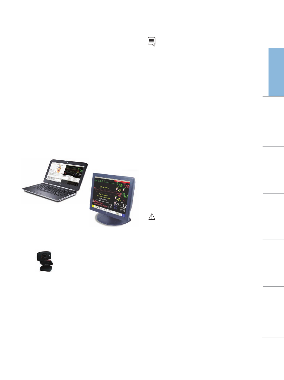
Instructor Laptop PC
– Touchscreen Patient Monitor (Complete Peripheral Kit Only)
– USB Webcam
– USB Hub
– Blood Pressure Cuff
– Set of Consumables
– Operating Software for the Instructor PC
– SimJunior Directions for Use (DFU)
Instructor PC controls simulations. It includes software programs for
creating and editing scenarios, as well as an application for debriefing
simulation sessions with video capture from a web camera and the
Patient Monitor.
Patient Monitor
.
s
r
o
ti
n
o
m
t
n
e
it
a
p
t
s
o
m
e
t
a
c
il
p
e
r
o
t
d
e
r
u
g
fi
n
o
c
e
b
n
a
c
It also doubles as a display for other functions, such as 12-lead ECG,
X-ray images, and lab results to view the patient’s case history.
Web Camera records video and sound of the simulation for use
during the debriefing session.
Setup Summary
Note: Refer to the SimJunior Quick Setup Guide for detailed
instructions on initial simulator setup.
1. Start the Instructor PC
– Connect the mouse and power supply to the computer and
power ON.
– Make sure that the SimJunior simulator icon is displayed on the
Instructor PC desktop
2. Install the USB hub
– Connect Power to the USB hub.
– Connect USB hub to Instructor PC
3. Connect the Patient Monitor Cables
– Put aside the software CD that comes with the monitor. DO
NOT INSTALL software CD.
– Route the cables through the Patient Monitor stand and connect
them to the corresponding outlets located at the bottom of the
screen.
-- Video cable
-- USB cable
-- Audio cable ( ck labeled monitor)
ja
-- Power cable
-- Secure the cables using the strain reliefs.
– Connect power cable to a wall outlet and power ON the Patient
Monitor.
4. Connect the Patient Monitor video cable and 3-way audio cable
(black mini jack with double wire) to the Instructor PC.
IMPORTANT: Do NOT connect the USB cable to the Patient
Monitor yet.
5. Set Up the Instructor PC for Extended Desktop Display to
Support the Patient Monitor.
– Right click on the instructor PC desktop
– In the drop down menu select
– In the displays>. – Click – The Instructor PC (display 1) should have a resolution of 1600 x 900. – The Patient Monitor (display 2) should have a resolution of 1280 x 1024. – Click 6. Connect the Patient Monitor to the USB Hub. I NSTRUCTOR PC T OUCHSCREEN P AT IENT M ONITOR Web Camera Intr oduction Standar d System Advanced System Manikin Setup Maintenance Spar e Par ts Tr oubleshooting Specifications