Dell PowerEdge 350 User Manual
Page 13
support.dell.com
Introduction
1-5
Table 1-1 describes the appearance and function of the front-panel indicators.
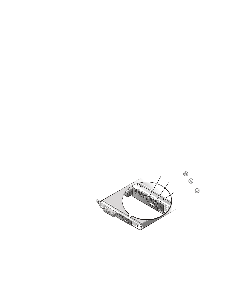
System Switches
Figure 1-5 shows the location of the three switches on the system front panel. To acti-
vate a switch, press the corresponding icon on the front panel as shown in Figure 1-5.
NOTICE: To prevent accidental system lockup, system reset, or false error
messages, do not press areas of the front panel other than the three switch
locations shown in Figure 1-5. Reserved test switches are located in other
areas of the front panel.
Figure 1-5. Front-Panel Switches
Table 1-1. Front-Panel Indicators
Indicator
Color
Function
Power
Green
Lights up when the system is connected to
an AC power source; blinks when the sys-
tem is in sleep mode
System fault
Amber
Blinks during system startup, or when a
system fault is detected
Hard-disk drive activity
Green
Blinks when hard-disk drive activity occurs
LAN 1 activity/link
Amber
Lights up when the LAN 1 connector is
linked to an Ethernet port; blinks when
activity occurs on this channel
LAN 2 activity/link
Amber
Lights up when the LAN 2 connector is
linked to an Ethernet port; blinks when
activity occurs on this channel
power switch
sleep switch
reset switch