Labconco SteamScrubbe & FlaskScrubbe Glassware Washers 44204 Series User Manual
Page 48
Labconco Glassware Washer Service/Technical Manual
42
CAUTION:
The voltage selected (115V or 230V) does not change the
acceptable AC mains voltage that can be connected to the washer. It only
selects the programs that are suitable for the identified voltage.
5. Press the ▼ button and TEMP UNITS will highlight.
6. Press ◄ or ► buttons to select either °F or °C which will be used on
the display to set and monitor temperature.
7. Press the ▼ button and DI PUMP ENABLE will highlight.
8. Press ◄ or ► buttons to YES or NO. Doing this allows the pure water
valve and pump to be disabled if pure water will not be used for rinse
cycles. It also prevents programming a cycle to have pure rinses if
pure water is not available.
CAUTION:
On PCB logic Revisions A and B, this setting MUST be YES. If the
customer does not have DI water hooked up, they need to be sure that all
rinses are TAP WATER RINSES!-
9.
Press the ▼ button and LIGHT will be highlighted on the display.
10. Press ◄ or ► to cause the light inside the tank on window models to be
turned on or off while the door is latched.
11. Press the ▼ button and LIQ DETERGENT OPT will be highlighted on the
display.
12. Press ◄ or ► to activate the control for the liquid detergent dispense
option if this accessory has been installed.
13. Press the ▼ button and FACTORY RESET will be highlighted on the
display.
14. Press ◄ or ► to select YES to erase all program set points entered by
the user and to restore all set points to the factory setting.
15. Press RUN to save all settings.
Replacing the Digital Display
1. Remove the Control Module from Control Panel.
2. Remove the four screws holding the display panel onto the Control
Module.
3. Pull the Display Panel to disconnect the pins from the PC Board and
remove it.
4. Fit the new Display Panel over the PCB placing the long pins in their
spots.
5. Secure the Display Panel with the mounting screws.
6. Place the Display Module into its housing and secure it with the six
mounting screws.
7. Test the unit in diagnostics.
Replacing the Button Pad
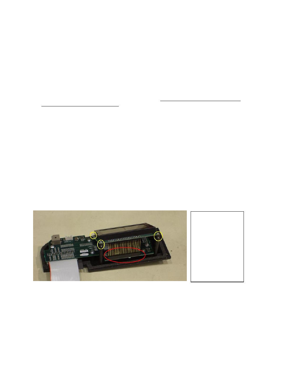
Figure 16
Left: Display Panel attached
to PC Board and Control
Module. The Yellow Circles
show where the Display
Panel’s Mounting Screws are
placed in the Control
Module’s bossing.
The Red Circle shows the pins
of the Display in the PC
Board’s connector. When
replacing the Display, be sure
all pins have been placed in
the PC Boards connector slots.