Appendix, 1 faults and warnings overview, Appendix 73 – Lab.gruppen PLM 20000Q User Manual
Page 79
Appendix
73
PLM Series Operation Manual rev 1.2.3
9. Appendix
9.1 Faults and Warnings Overview
Fault or warning conditions are indicated by the LED shown in Figure 7-3 on page 34, and also by LEDs associ-
ated with the inputs and outputs on the PLM. As the LEDs indicate several types of faults or warnings, a
brief textual description of the fault or warning is provided on the LCD display. Section 7.8.2 on page 34 details
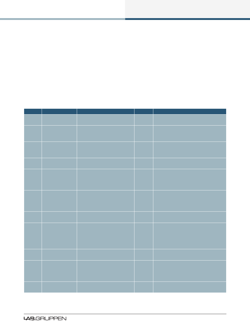
the fault and warning indications that appear on the front panel. Table 9-1 lists the events that may have
triggered each fault or warning condition.
Model
Displayed Text
Event Log Text
Category Description
ALL
AMP CH. MUTE
Amp Channel Mute
Mute
The audio signal has been muted in the
power output stage.
ALL
ANALOG IN
FAULT
Frame Fault: Analog Input
Fault
The analog input signal is corrupt due
to DC on the analog input, or there is an
issue with the internal A/D converter.
20000Q ATL ACTIVE
N/A
Warning
The output power is limited due to high
amplifier channel temperature - the amp
channel temperature limiter is active.
ALL
AUDIO FAULT
Frame Fault: Audio Interface
Fault
An internal audio fault has arisen and the
unit needs servicing.
20000Q BEL ACTIVE
N/A
Warning
Breaker Emulation Limiter present as the
nominal current reached. Improve the
power distribution and adjust the BEL
settings.
ALL
CAL ACTIVE
n/a
Fault
Ensures that the PLM’s power output
stages are not overloaded. This should
never happen during normal program
material.
20000Q CHECK AC
MAINS
Frame fault: Check AC Mains
Fault
The PSU received unstable mains, check
the mains configuration.
ALL
CLOCK SLIPPING
AES Clock slipping
Warning
The AES or Dante clock is slipping; verify
clock selection / generator. This will
cause high THD on signal, and if Dante
is running will result in an unstable signal
distribution.
ALL
CTRL OFFLINE
N/A
Warning
The PLM is no longer able to communi-
cate with the Lake Controller.
ALL
CURRENT CLIP
n/a
Clip
PLM’s power output stage current has
exceeded the fixed safe maximum and
the Current Peak Limiter has become
active to limit it.
ALL
INPUT CLIP
n/a
Clip
The input signal level is too high and is
causing clipping at the input stage