Hase Ottawa User Manual
Page 38
38
5.
Flue Pipe Connection
The stove has to be connected to the chimney with
a flue pipe with an inside diameter of 15 cm. Please
ensure that all pipe pieces are tightly fit at the con-
nection junctions. We recommend using elbow pi-
pes with cleaning hatches.
CAUTION!
The flue pipe must be well sealed at the
chimney entrance and cannot project into
the inner cavity of the chimney; otherwise
the flue gas venting will be impaired (Fig.
1).
fig. 1
CAUTION!
When operated as a direct vent stove, the
flue pipe connection to the chimney has
to be gas proof and sealed with a suitable
sealing cord and heat-resistant silicone.
Ensure that all connections points at the
flue pipe connecting piece and at multip-
le section flue pipes are sealed with Hase
sealing paste (see Installation Instruc-
tions).
6.
Combustion Air Connection
The combustion air in the fire box is solely supplied
by a customer-provided supply air pipe and the Hase
Air System pipe connections. The connecting piece
for the Hase Air system is located on the back side
of the stove. The sealed pipe connections are either
routed directly to the outside or connected to a sui-
table air/flue gas system (AFS). Another option is to
provide the supply air from a room that has its own
independent outside air supply (e.g. cellar or base-
ment).
The customer-provided air inlet duct has to be con-
structed using plain, smooth pipes (steel pipes in
compliance with 24145, drain pipes in accordance
with DIN 19534 and EN 1451B) with a minimum dia-
meter of 100 mm, a maximum of two bends and a
permissible total length of 4.5 meters. Designs using
longer piping and pipes with more than two bends
have to be verified through calculations. The required
supply of combustion air has to be ensured (see Part
1 “Technical Data”). The air supply pipe has to be
equipped with suitable inspection openings for ins-
pection and cleaning purposes. The entire air supply
pipe has to be airtight. We advise discussing this
with your local planning officer. At the air inlet ope-
ning, we recommend installing an animal protection
screen with a mesh size of 10 mm.
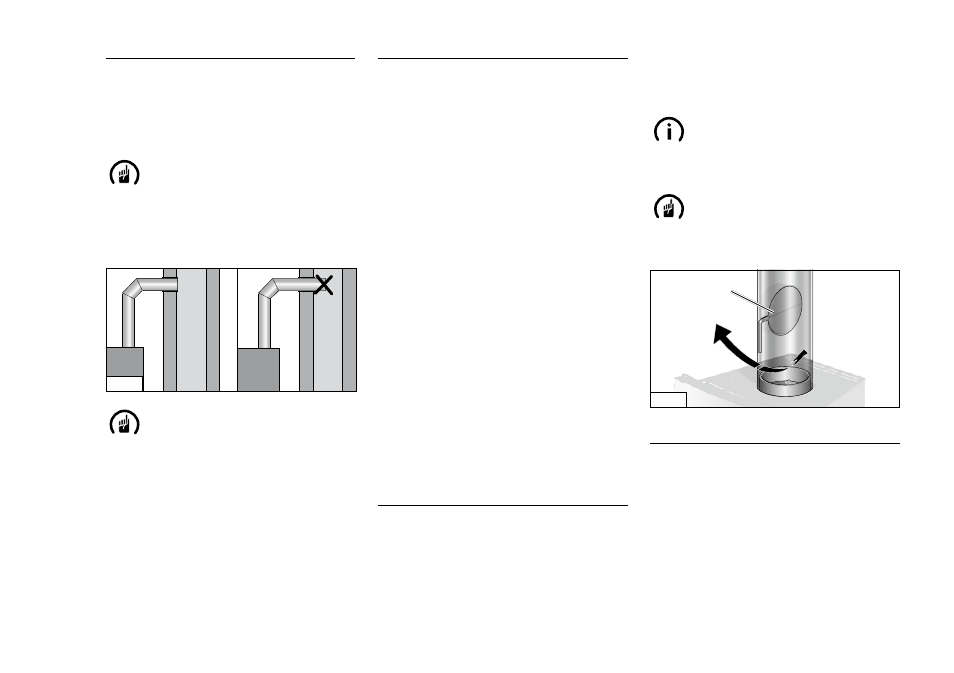
7.
Butterfly Valve
The butterfly valve (Fig. 2/a) is an optional control
element. It is fitted in the flue pipe and used to re-
gulate the flue gas flow, and can thus slow down
the burning-off process. When the handle’s posi-
tion is diagonal to the flue pipe, the flue gas flow
rate is turned to minimum. In the case of increased
pump pressure in the chimney unit, we recommend
installing a butterfly valve. Please comply with the
country-specific legal regulations.
NOTE!
Make sure the butterfly valve (Fig. 2/a) is
open before opening the fire box door duri-
ng the burning phase.
CAUTION!
With direct vent stove operation, the instal-
lation of a butterfly valve is not permitted
due to the required air tightness
a
fig. 2
8.
Regulating the Combustion Air
We develop an individual air duct routing for each
Hase stove model, to ensure that the necessary
combustion air is guided to the right areas in the fire
box.
The primary air supplies the glowing embers with
oxygen. The secondary air is heated and guided to
the flame area. It minimises the formation of soot on
the fire box windows.